Release Notes: Altair Feko 2024.1
Altair Feko 2024.1 is available with new features, corrections and improvements. It can be applied as an upgrade to an existing 2024 installation, or it can be installed without first installing Altair Feko 2024.
Feko is a powerful and comprehensive 3D simulation package intended for the analysis of a wide range of electromagnetic radiation and scattering problems. Applications include antenna design, antenna placement, microstrip antennas and circuits, dielectric media, scattering analysis, electromagnetic compatibility studies including cable harness modelling and many more.
newFASANT complements Altair’s high frequency electromagnetic software tool (Altair Feko) for general 3D EM field calculations, including, among others, special design tools tailored for specific applications like complex radomes including FSS, automated design of reflectarrays and ultra-conformed reflector antennas, analysis of Doppler effects, ultrasound systems including automotive or complex RCS, and antenna placement problems. Advanced solver technologies like the MoM combined with the characteristic basis functions (CBFS), PO/GO/PTD, GTD/PO and MLFMM parallelised through MPI/OpenMP, being some of them especially efficient for the analysis of electrically very large problems.
WinProp is the most complete suite of tools in the domain of wireless propagation and radio network planning. With applications ranging from satellite to terrestrial, from rural via urban to indoor radio links, WinProp’s innovative wave propagation models combine accuracy with short computation times.
WRAP is a comprehensive tool for electromagnetic propagation, antenna collocation and spectrum management. WRAP combines propagation analysis, often over large areas with many transmitters and receivers, with system analysis to include complex non-linear equipment properties.
Highlights of the 2024.1 Release
The most notable extensions and improvements to Feko, newFASANT, WinProp and WRAP in the 2024.1 release.
Salient Features in Feko
-
Model protection was extended to allow a custom 3D representation to be shown when a protected model is imported by a client. The 3D representation does not get meshed and does not form part of the simulation. The custom representation geometry is specified by the model creator and replaces the grey translucent box that is displayed for protected models without a custom representation geometry.
Figure 1. On the left, an example of a protected model which is only visible if the password is known. On the right is the representation geometry that will be visible to the client. Note that representation geometry is not meshed. 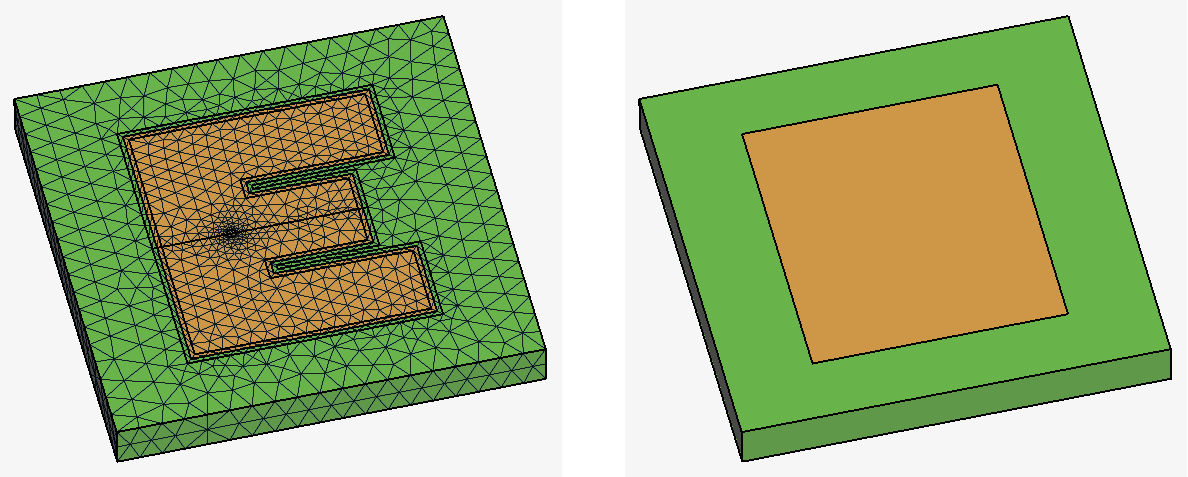 Protected models can now be imported and placed on other geometry and the meshing will take this into account.
Figure 2. On the left, the model where the protected model will be imported. Note that overlapping areas need to be substracted. On the right, the protected model was imported into the model and was meshed. 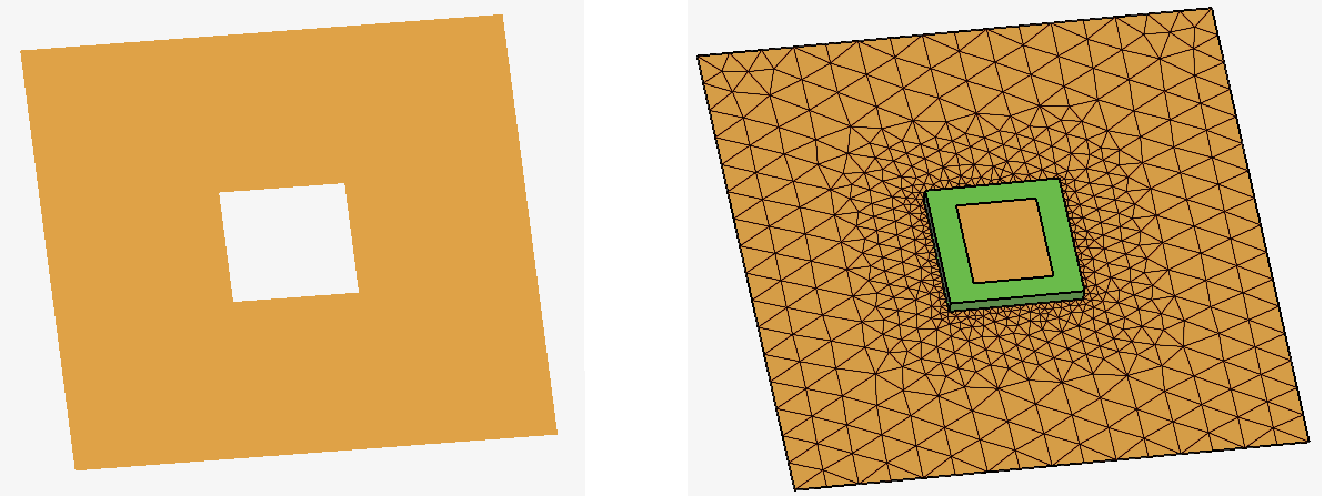
Workplanes and ports in a protected model can be exposed allowing clients using the protected model access to the workplanes and ports. Sources and loads can now be added to these exposed ports in the protected model.
When using a protected model, S-parameter configurations and near field requests are now supported.
- The following components were added to the component library:
- Predefined EMC test setup typical of standard GB/T 18387 EMC measurements using a loop EMC antenna.
- Multi-band stacked patch antenna, such as typically used for global navigation satellite system (GNSS) applications.
Figure 3. The dual band GNSS stacked patch antenna and EMC test setup GB/T 18387 EMC (loop antenna) available in the Feko 2024.1 component library. 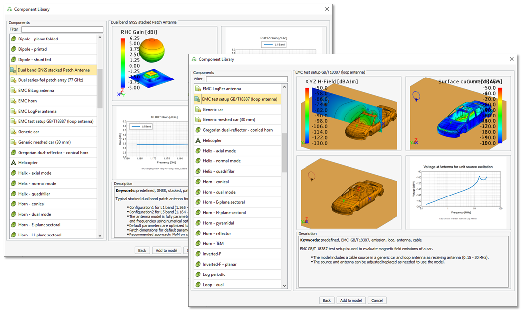
- AMD AOCL libraries (optimised for AMD processors) can now be enabled when running the Feko Solver.
Salient Features in WinProp
- Beam steering in 5G networks is now supported in ProMan,
where it dynamically directs radio signals towards specific users, improving signal
strength and quality. Beam steering is based on phased array antennas, where the signal
phases fed to the antenna elements are adjusted to form a focused beam in the desired
direction and can track the movement of users.
Figure 4. The data beam from the antenna array serving a user at different times. 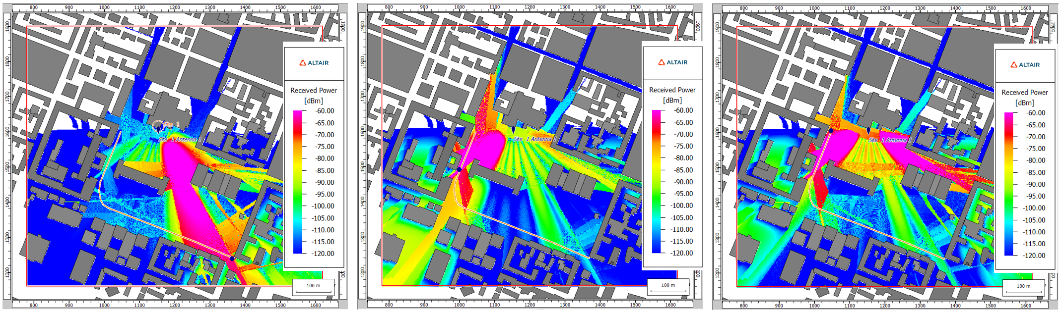
- The automatic report generation were extended to include a project summary along with
the exported results and 3D view.
Figure 5. An example of an exported Microsoft Word report. 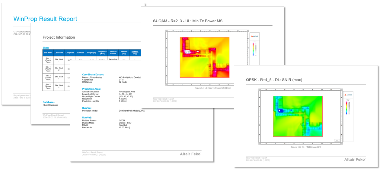
-
Extended the balloon tip feature to create a reference point with each click. The balloon tip for the marker shows the result value and the coordinates at this point. A marker is indicated by a red
X
and can be deleted by clicking on the marker. When new results are loaded or if the marker is outside the simulation area, the marker info in the balloon tip is updated accordingly.Figure 6. An example of multiple markers with balloon tips displaying the result value (where relevant) and coordinates. 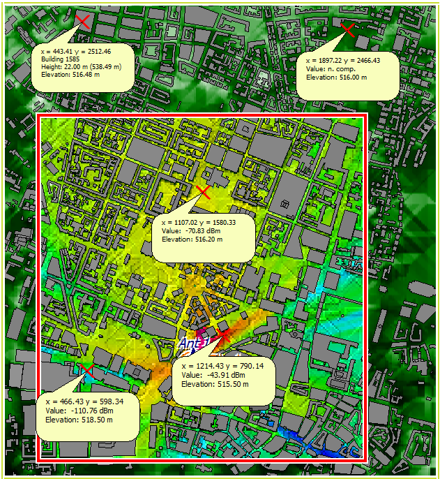
- The computed prediction results that can be requested additionally, now include
superposed received power where support was added for coherent superposition (phase
considered). Up till version 2024, only incoherent superposition (power sum, phase
ignored) was supported.
Figure 7. An example showing the superposed received power (coherent superposition) for an indoor propagation scenario. 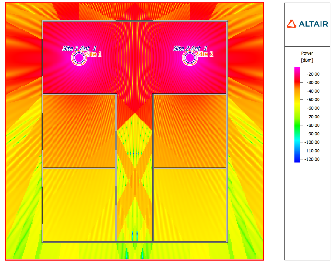
- Multiple mobile-station antenna configurations are now supported in a project for point and trajectory mode.
Salient Features in WRAP
- The coverage result levels can now be inverted for many types of results. For example,
it is now possible to visualise the required antenna height above and below a certain
level. Some result types can now generate more information, both in the result information
dialog and printout.
Figure 8. On the left, an example of the original coverage results. On the right, coverage results were inverted. 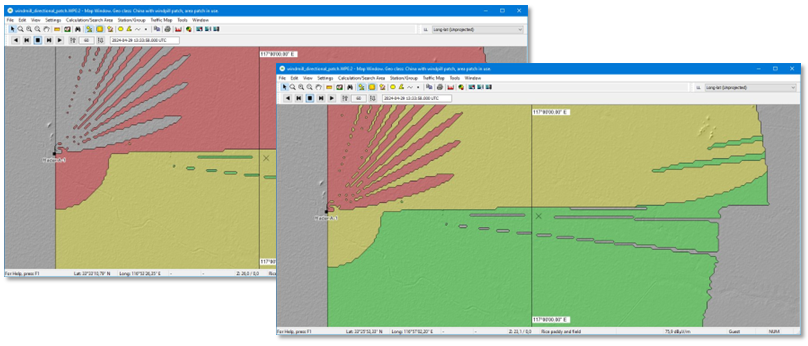
- The Interference tool was extended to include typical stations in the calculation. You
can also now perform interference calculations for
typical
station types (they can be created without any particular geographical coordinates, may have predefined service area).Figure 9. On the left, an example of a fixed station and on the right, an example of a typical station. 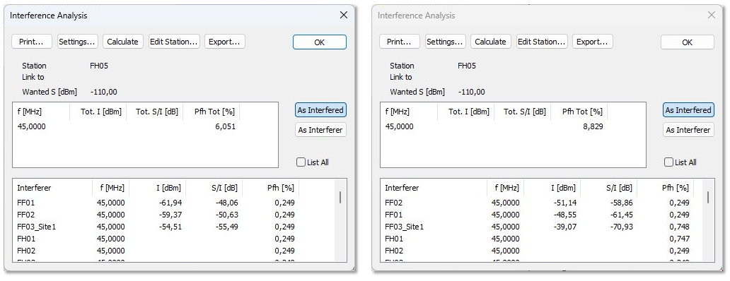
Feko 2024.1 Release Notes
The most notable extensions and improvements to Feko are listed by component.
CADFEKO
Features
- The new mesh engine that was introduced in CADFEKO 2023.1 is now the official mesh engine without fallback. The legacy mesh engine has been removed.
- The legacy cfx converter now supports a --verbose option. This will give additional information about each phase of the conversion and can be used when giving feedback to the Feko support team. For large files it is best to pipe this output to a text file.
- Extended model protection with the following:
- Ports in a protected model can be exposed allowing client models to add sources or loads directly to the ports inside the protected model.
- Workplanes in a protected model can be exposed allowing client models to use them. This replaces the single Orientation Workplane that could previously be defined for a protected model.
- Representation geometry allows the creator of the protected model to design a custom 3D view representation of the confidential model. The representation geometry will be shown in the 3D view of the client model when the protected model is imported.
- Added support for near field requests when using protected models.
- Added support for S-parameter configurations in client models that include imported protected models.
- Improved meshing of client models that include imported protected models to allow placement of a protected model directly onto a component in the client model.
- Cartesian boundary near fields computed without samples on the edges of the bounding box can now be used when defining an impressed near field source or receiving antenna.
- Changed the faceted UTD ray contribution settings to include corner diffraction and creeping rays by default.
- Added surface transmission to the ray contribution options for faceted UTD.
- Added additional checks for improved schematic link validation.
- Reworked drag and drop functionality. Dropping onto a item, "Move In" will move into that entity if valid and geometry groups can be dragged into combined geometry.
- CADFEKO_BATCH now supports changing variables in groups from the command line. The syntax of referencing a variable in a group is through a dot between the group name and the variable. Nested groups are also supported.
- Added a predefined EMC test setup typical of standard GB/T 18387 EMC measurements using a loop EMC antenna to the component library.
- Added a multiband stacked patch antenna, such as typically used for global navigation satellite system (GNSS) applications, to the component library.
- Added the Create Coaxial Connector Feed macro that creates a coaxial connector on a finite substrate. This application macro uses three defined named points in the model to define where the coaxial connector will be located. The coaxial connector is defined using an outer diameter, inner diameter, coaxial length and insulating dielectric.
- Upgraded the ECAD import library used by CADFEKO to the latest version provided by Altair PollEx.
Resolved Issues
- Fixed an issue with license checking that could cause a license error when opening CADFEKO with an existing project if managed licensing is used. This problem also caused the model creation phase of the parameter sweep application macro to fail for users using managed licensing.
- Fixed a crash that could be encountered when using the Generate Antenna Array macro.
- Resolved an assertion failure when dismissing the Executing PREFEKO window if it was left open from a mesh import into a previous project.
- Fixed incorrect .pre file writing for loads on cable ports under certain conditions. The circuit was not correctly passed to the solver, causing the solver to issue Warning 38935: A SPICE circuit element has an unconnected floating terminal. Please verify circuit connections.
- Fixed a crash when converting a legacy model that had geometry operations that could no longer be executed successfully.
- Resolved issues with rectangle selection of model mesh elements:
- Fixed a crash when deleting mesh triangles that were selected using rectangle selection.
- Resolved an issue where mesh normals would not be reversed for elements that were selected using rectangle selection.
- Resolved an issue with the edge loop selection tool that could cause the application to hang or crash.
- Fixed a memory performance issue with the project geometry operation that could result in a crash.
- Fixed a framework memory allocation assertion failure which is triggered when running a Lua script that loads many large models consecutively.
- Fixed crashes when creating geometry in the negative symmetric regions.
- Fixed an intermittent crash when closing dialogs that dynamically draw contents.
- Fixed an intermittent crash with dialogs containing tab widgets.
- Resolved an issue with the legacy cfx converter where errors would not be reported correctly. This could have resulted in a converted model containing no geometry without any errors being issued during the conversion process.
- Fixed an undo bug that could result in a crash when saving the model.
- Fixed undo bug that could cause meshing to stop working until the model is re-opened.
- Resolved an assertion failure when accessing the properties of a geometry group.
- Fixed a hang when dragging a geometry group into itself.
- Resolved an assertion failure when attempting to transform a group inside combined geometry such as a union.
- When separating a part, any groups that were inside will also be moved out of the part and no longer be deleted.
- Resolved an assertion failure when projecting geometry and clicking on a preview in the 3D view while the Project dialog is open.
- The target of projected geometry now gets indicated by a T icon in the model tree.
- The target of projected geometry can be updated by selecting Update Target on the right-click context menu of the intended target geometry entity inside the projected geometry part.
- Resolved an issue where changing the solution configuration global/local settings from the cogwheel icon on the model tree (Configuration tab) could result in a crash.
- Improved component library importing stability through the GUI to prevent a crash that could be encountered when adding a predefined component to a project.
- Avoid a crash when opening loft properties.
- Avoid a crash when dragging and dropping geometry elements in the model tree.
- Avoid a crash on Linux when changing number of parallel processes.
- Resolved an issue that prevented the user from specifying more than 99 parallel processes on the Component Launch Options dialog.
- Fixed an issue where a .pre file overwrite message appeared unexpectedly when saving a model while it was being meshed and then CADFEKO seemed to become unresponsive.
- Resolved an issue that no prompt to save would be given when loading a model from the recent file list and any changes to the current project would be lost.
- Fixed the file browser to open at the location of the most recent file that was used.
- Closing the application with multiple open tools will now close all of them.
- Added a mechanism that will undo a process that failed for an unexpected reason. An error message is given with an option to attempt to fix the model.
- Improved the robustness of .cfm file writing to avoid unexpected errors when running the solver. Previously, if new line characters were used in variable descriptions, errors such as Error 30410: An unsupported card in the *.cfm include file would be triggered by the solver.
- Improved mesh growth around edge and microstrip geometry ports for cases where the edge is very short relative to the wave length. This will generally result in improved accuracy when using edge ports.
- Resolved an issue with meshing where wire mesh sizes were not being affected by surrounding geometry.
- Added a verification warning when overlapping regions are detected during the meshing process.
- Fixed a problem where renaming a variable could cause the cable schematic to change.
- Added verification so that model status warnings get triggered for empty labels on far field, near field and current requests that are set to be scoped by topology labels.
- Models containing polygonal model mesh UTD plates with more than ten corners can now be loaded and visualised.
- Significantly improved the loading performance of models that utilise periodic boundary conditions.
- Fixed the loading performance and a possible crash when opening large models with auto-meshing disabled and no frequency set.
- Improved the performance of face/edge deletion for large models.
- Resolved an issue where an error message got issued when creating an S-parameter configuration and using a valid variable as port impedance. A known bug still affects the dialog when modifying an S-parameter configuration that references variables. A workaround for this problem, for the variables to be resolved correctly, is to modify the S-parameters from the Configuration tab in the model tree.
- Improved the performance of the Executing runfeko dialog for models where many lines of output are generated. Before, it could have happened that all the lines did not get displayed correctly, with some text towards the end of the output appearing as blank space.
- Resolved an issue when scaling model meshes that any waveguide ports applied to it did not get scaled correctly when preparing the solver input. This caused the solver to issue Error 4793: The surface area of the triangles of a waveguide port does not correspond with the waveguide port definition. The correct dimensions are now used.
- Fixed the rendering of waveguide ports on parts with mirror transforms and mesh parts with scale transforms.
- Resolved an issue where the dielectric surface impedance approximation could not be applied to model mesh faces. The face medium of a model mesh face can be set to dielectric surface impedance when the front and back mediums are the same dielectric or dielectric and free space.
- Resolved a crash when importing a CADFEKO model (.cfx file) and choosing to merge identical media.
- Fixed a CADFEKO model (.cfx file) import failure when merging identical variables.
- Fixed the .pre file writing of media used in protected models.
- Added a verification message if an included protected model configuration does not have a frequency defined.
- Removed a verification warning about the
MaxIdenticalDistance
setting being out of sync between a model and a protected component. - Resolved various issues that could be encountered when undoing or redoing enabling or removing model protection. These actions are no longer placed on the undo/redo stack.
- Fixed a bug that would cause POSTFEKO to stop checking for file changes if the file uses model protection.
- Corrected the preview of transforms applied on protected model geometry.
- Corrected validation for schematic link port references.
- Resolved an issue where redundant automatic schematic links were being written to the .pre file.
- Added verification of the separation distance for schematic links that define the connection between cables and geometry.
- Resolved a crash that could happen when using Undo after running a script.
- Fixed script recording and undo/redo when setting the target of the project and subtract operators.
- Fixed an issue with the API where running a macro recorded script that duplicates geometry would fail with the error attempt to call method 'DuplicateTopology' (a nil value). The DuplicateTopology process is now available via automation.
- Fixed macro recording to record moving geometry using drag and drop.
- Avoid the double display of shortcut keys in the tooltips of the script editor.
EDITFEKO
Features
- Cartesian boundaries computed without samples on the edges of the bounding box can now be used when defining an impressed near field source.
- Changed the UT card faceted UTD ray contribution settings to include corner diffraction and creeping rays by default.
- Extended the UT card with the Surface transmission ray contribution option for faceted UTD.
POSTFEKO
Features
- Added the capability to plot near field results on 2D graphs when using protected models.
- Improved the 2D graph handling of near field results requested below a ground plane. Near field values for points that fall below the ground plane will no longer be plotted on 2D graphs.
- Added the Export Graph Data to DAT File macro. This application macro creates a .dat file in the specified output folder for each trace on every Cartesian and polar graph in the current project.
Resolved Issue
- Resolved an issue where surface graphs did not update correctly to show the updated plot range after changing the independent axes.
Solver
Features
- Added support to specify materials (including reflection and transmission effects with multilayer thin dielectric sheets and coated PEC, characterised surfaces and surface impedances) when using Faceted UTD.
- Faceted UTD enables corner and tip diffraction and creeping waves by default.
- Dramatically improved the speed of the processing phase for models including many wire segments.
- Near field requests may now be calculated in models which include protected parts. Any near field points on or close to protected parts will not be calculated.
- Model decomposition data may now be exported to a .sol file file during a simulation that includes protected models.
- Error estimate may now be requested for a simulation that includes protected models.
- Currents may be requested when simulating a model that includes protected components.
- Updated MPICH to version 4.2.1 on Linux.
- Upgraded the Intel MPI library to version 2021.12.1 for Windows and Linux.
- Upgraded to MUMPS v5.7.1c.
Resolved Issues
- Improved faceted UTD capabilities for complex models where the number of triangles and/or observers is large.
- Fixed a bug that caused internal errors for faceted UTD problems where more than one interaction is requested.
- Resolved an issue where wires connected to faceted UTD triangle edges were incorrectly reported as segmentation rule violations.
- Fixed a bug (memory out-of-bounds) for sequential stabilised MLFMM with multiple dielectrics.
- Improved the program flow and setup of the internal near field aperture to equivalent spherical mode sources transformation phase. This avoids the previous incorrect reporting of Warning 53699 (mismatch in frequency, spherical mode data) and Warning 40147 (near fields are in spherical mode cut-off region).
- Fixed various segmentation violations that could occur when using a GPU for RL-GO problems.
- Enforce CUDA compute version checks to agree with what is reported in the manual.
- Issue a note when there are no MoM segment/triangle basis functions associated with the specified labels for export to a .sol file.
- Resolved an error when using CFIE with periodic boundary conditions.
- Fixed a bug in the execution of consecutive far field requests where a change in label selection (OF card) did not trigger a proper re-evaluation of the solution parameters.
- Improved result consistency when using MoM with higher order basis functions and EFIE/CFIE.
Shared Interface Changes
Support Components
Features
- Adjusted AMRFEKO reference levels to provide more accurate converged results when using the low threshold settings.
- Added support to enable AMD AOCL libraries when running a simulation. See the Feko User Guide for more details on setting the environment variable ALTAIR_EXT_MATH_API.
- The Get to Know the New CADFEKO Interface document was removed from the installation. For more information on migrating legacy CADFEKO scripts to the new CADFEKO API format, refer to the Altair Community article.
Resolved Issue
- Fixed an issue that may have resulted in a Signal 22 error when importing .fek files that use 3D anisotropic media.
WinProp 2024.1 Release Notes
The most notable extensions and improvements to WinProp are listed by component.
General
Features
- Extended the wireless standard definition files .wst in Example A07 (available in /help/winprop/examples/ExampleGuide_models) for 5G, LTE, 802.11be, 802.11ax and UWB.
- Upgraded the Intel MPI library to version 2021.12.1 for Windows and Linux.
ProMan
Features
- Added support for the MS azimuth orientation to be considered in case of full polarimetric projects to account for the polarisation impact on the electric field vector.
- The MS antenna pattern can now be displayed in the 3D view.
- Added support for beam steering in 5G networks based on phased array antennas, where the signal phases fed to the antenna elements are adjusted to form a focused beam in the desired direction and can track the movement of users.
- Resolved an issue where rays were not displayed for urban models with topography and calculating point mode.
- Extended the report generation to include project information.
- Added a button on the Edit Project Parameter dialog (Simulation tab) to restore the prediction area to the default size in the case of area mode.
- Added the option for coherent superposition of the transmitters to compute the total received power as additional output in a project.
- Extended the balloon tip feature to create a reference point with each click. The balloon tip for the marker shows the result value and the coordinates at this point. A marker is indicated by a red
X
and can be deleted by clicking on the marker. When new results are loaded, the marker info in the balloon tip will be updated accordingly. - Added support for multiple mobile-station antenna configurations in a project for point and trajectory mode.
- Results, databases, antenna patterns and measurement files in ProMan are now added directly to the zip archive without first copying the files into a temporary location when exporting projects.
Resolved Issues
- The minimum distance for the dominant path model was reduced from 1 m to 1 cm.
- Resolved an issue where selecting a .ffe antenna pattern for a transmitter resulted in an error dialog being displayed.
- Resolved an issue where the degree symbol was not displayed correctly on certain dialogs, for example, the Transmitter Type dialog and Cell dialog.
- Resolved an issue that could have occurred where pixels without topography were not disabled for computations, resulting in computations not progressing after a certain percentage.
- If network planning based on traffic is selected but no applications are defined, an error message is now displayed. In the past, this would have resulted in a crash.
- Resolved an issue where text was cut off on the Edit Project Parameter dialog (Computation tab) and Parameter: Ray Tracing dialog.
- The rural ray tracing model (RRT) has now been enabled for satellite transmitters that are typically outside the given topographical map. Furthermore, a problem with the computation of the direct ray has been fixed, based on which the direct ray was partly missing in the computed results.
- Resolved a crash that could have occurred when opening a database and viewing it in the 3D view.
- Added satellite, gps_satellite and external Tx types to .csv export and import.
- The breakpoint distance is no longer checked for the Deterministic Two-Ray model, as it is not used in the computation.
- Satellite transmitters are now displayed in the 2D view. Depending on the position, you might need to zoom out to view the satellites projected onto the 2D view.
- If Superposed Received Power is requested, the progress bar remains open if there is an error during the propagation phase.
WallMan
Feature
- Upgraded the ASAM OpenDrive library in WallMan to support the import of traffic signs, which allows you to specify large and complex road networks.
Resolved Issues
- For the conversion of topography and clutter pixel maps in WallMan and ProMan the extract of a part directly at the conversion process is now possible.
- Resolved an issue where vegetation and furniture materials were exported incorrectly to .ida files.
- Resolved a crash that could have occurred when opening a database and viewing it in the 3D view.
Application Programming Interface
Feature
- Modified WinProp API structs to use static instead of dynamic memory for strings.
newFASANT 2024.1 Release Notes
The most notable extensions and improvements to newFASANT are listed by component.
Solver
Feature
- Upgraded the Intel MPI library to version 2021.12.1 for Windows and Linux.
WRAP 2024.1 Release Notes
The most notable extensions and improvements to WRAP are listed by component.
General
Features
- Improved the default map window by setting GrayScaleRelief as the default raster background for a new empty map. The new default setting improves map visibility and reduces the effort to set the map raster background for every new map window. In previous releases, the default map window raster background was always empty even if default Geodata was installed. The raster background then had to be set for each new map window.
- The coverage result levels may now be inverted for many types of results. For example, it is now possible to visualize the required antenna height above and below a certain level. Some result types can now generate more information, both in the result information dialog and printout.
- Coverage results can now be shown as non-interpolated in the map viewer. This may result in a cleaner result image if the result areas are very narrow.
- Heights below -600 meters are now considered valid; the lowest valid height value is now -9998 meters to allow for calculations on planets other than the Earth.
- Extended the function in the Interference tool to include typical stations in the calculation.
- The varying frequency separation has been given the additional options Round and Truncate to closest allotment channel when calculating the frequency separation. The option None corresponds to the single Varying option available previously.
- Added a warning if the source directory contains files with different resolutions. Raster file types that are checked are ESRI Arc/Info GRIDASCII, GeoTIFF, and clutter files in TIFF with TFW format.
- Upgraded the Intel MPI library to version 2021.12.1 for Windows and Linux.
Read the Feko Installation Guide Section 6.2.1 and Section 6.2.8 if you need to update Feko and WRAP and want to keep the same Databases and Geo maps settings as an older version of WRAP.
These steps are only applicable if you have an existing installation of Altair Feko with WRAP installed and updating to a new major version. If you are updating the minor release or installing the patch, then WRAP will keep the same previous settings by default as long as the Feko version and installation are the same.
Resolved Issues
- Fixed a bug which, in some cases, could move the terrain rasters one pixel to the south.
- Resolved an issue where a large, nearby object in an area patch was not included in the terrain profile used for calculations. Also, the use of vegetation zones for area patches without explicit DEM values for WRAP FM was corrected.
- Resolved a crash when calculating Coverage, No of Servers, Interference limited for uplink.
- Resolved a crash that could occur when calculating on radio links longer than 100 km.
- Resolved an issue that may have caused a simulation to go into an endless loop in the case of calculating atmospheric attenuation for a slant propagation path and the smooth earth curvature blocking the LOS.
- Resolved an issue that prevented a custom ellipsoid from being entered.
- Added a warning when an invalid MGRS or GARS coordinate is entered in the position dialog or read during station and area import.
- Added support to pan and zoom while an area is drawn.
- Fixed a bug that prevented the profile from being shown if both the tx and rx positions were already set in a map.