
Twin Activate Blocks
Overview of how blocks are used in Twin Activate.
A Twin Activate Model is an interconnection of blocks. Most Twin Activate users do not need to develop new blocks because Twin Activate provides a large number of blocks through different palettes. However, advanced users might need to develop new specialized blocks. These blocks can be placed in new libraries and distributed to other users.
Blocks in Twin Activate can be constructed based on other blocks. A masked Super Block, for example, behaves almost like any other block in the Block Diagram Editor (BDE); the only difference is that the diagram inside the Super Block can be visualized and edited only using the Enter Masked Super Block contextual menu item. In the case of a library block, the block must be first inlined to enter the Super Block.
A block can also be defined through a diagram inside, similarly to a Super Block, but without any associated graphical information. These blocks are called programmable super blocks. The content of the block is defined via OML scripts using special APIs instantiating and connecting blocks to define the inside diagram. At the BDE level, programmable super blocks are indistinguishable from basic blocks. In the absence of graphical information concerning the inside diagram, the Enter Masked Super Block operation is not available. In fact, this operation cannot apply even if graphical information were available, because the content of a programmable super block might depend on block parameters. For example, a block parameter can define the number of times a structure is repeated in the diagram. The parameter values not necessarily being available in the BDE, the diagram structure is not even known.
A basic block defines its behavior directly through a simulation function. Simulation functions are defined as C functions in most cases but they can also be defined in OML. Simulation functions can be developed first for CCustomBlock or OMLCustomBlock and tested before being used in the definition of a new basic block.
Block Simulation Function
A block communicates with other blocks via the regular input and output ports and activation input and output ports..
Signals associated with regular input and output ports can be of type matrix with real, complex, or integer data types. The activation input and output ports, on the other hand, transmit only events (which are also called activations).
A block can have several regular and activation input and output ports. A block can also have continuous-time, discrete-time states, and zero-crossing surfaces. Of course, a block does not need to have all of these elements.
The behavior of a Twin Activate block is basically governed by the way it is activated. The block is activated when it receives activation on its activation input ports. If the block does not have input activation, it can be activated by inheritance. In this case, the activation input ports are added by the Twin Activate compiler to the block. The block can also be defined as being Always active.
A block can be activated in many different ways. In the following, a number of scenarios are presented.
Discrete-Time Activation or Events
Continuous-Time Activation
If the source of the activation is always active, then activation occurs over time interval and not at specific time instants similar to discrete-time events. In continuous-time activation, the output computation can be represented with:
During a continuous-time activation, no state update and no event-programming is performed. Discrete-time states z, mode variables and simulation phase stay unchanged. On the other hand, the continuous-time state follows the differential equation:
Zero-Crossing Function and mode variables
Twin Activate provides several numerical solvers, including fixed step-size and variable step-size solvers such as Lsoda and Radau. Variable step-solvers adjust the integration step size during the integration to provide a faster simulation without compromising the precision in the solution.
If the differential equation represented by the diagram is not smooth enough, the variable-step solvers reduce the step-size to cope with the non-smoothness or even discontinuity. If foutput or fcontinuous is not smooth (continuously differentiable) at some points, then the mode variable is used in such way as to make sure the numerical solver never encounters these discontinuity points inside the integration interval. Consider the following example:
This function implements the absolute value function and is not differentiable at u = 0. In this case, a mode variable can be defined to specify at the start of the integration period whether u is positive. To make sure the integration stops when the sign of u changes, a zero-crossing surface is introduced at zero. Here, the zero-crossing surface is u = 0. During the integration period (which could end because of the zero-crossing), the output y is computed as follows:
When the zero-crossing is detected, the numerical solver stops and the mode is recomputed; then the integration continues. The computation of the mode and the zero-crossing surface are performed by the block. The block can be called in different situations or phases. In some phases, such as during the numerical integration, mode variables are fixed and in other phases, modes are updated. For example, when an event activates the block, mode variables can be updated. The phase variable is not directly accessible. You can check if mode variables are fixed or not by using the macro isModeFixed(block).
When a variable step solver integrates a model, a time interval might be repeated several times until the solver accepts the step and starts another step. In most situations, you do not need to worry about these intermediate repeated calls. In some cases (e.g., when the output of the block is displayed) you can ignore these calls. To filter these calls, use the macro isinTryPhase(block). This macro uses the phase variable to find out whether the call should be ignored. It is important to indicate that mode variables are used only when the numerical solver is variable-step.
Zero-crossing functions can also be used to generate discrete-time events. When a zero-crossing surface function inside a block crosses zero, the block is activated with a nevprt = −1, i.e., at this event time te, fdiscrete is called with nevprt = −1. This type of activation is used, for example, in modeling a simple bouncing ball that will be presented later.
Simulation Function Implementation
The simulation function is normally written in C, but can also be written in OML. This function defines the behavior of the block during the simulation.
MyNewBlock(vss_block *block, int flag)vss_block Structure
struct vss_block {
    ....
    BlockInputX input;
    BlockOutput output;
    BlockEventInput evinput;
    BlockEventOutput evoutput;
    SimFunction sim;
    BlockState state;
    BlockDState dstate;
    BlockODState odstate;
    BlockConstraint constraint;
    BlockRpar rpar;
    BlockIpar ipar;
    BlockOpar opar;
    BlockZcross zcross;
    BlockMode mode;
    SCSPOINTER_COP *work;
    SCSINT_COP ajac;
    BlockName name;
    SCSINT_COP dept;
    SCSSTRING_COP blocktype;

    SCSPOINTER_COP simulatorVars;
    .....
};typedef struct {
....
SCSINT_COP nout;
SCSINT_COP outdim;
SCSINT_COP *outsz;
SCSINT_COP *outtyp;
SCSPOINTER_COP *outptr;
....
}BlockOutput;#define SCSREAL_COP doubleint *odt=GetOutType(block,2);Flag
Flag is an integer (or more precisely an enumeration) value indicating the job for which the block has been called by the simulator. Blocks can be called with different flags to perform different operations. For example, the block can be called with flag= VssFlag_OutputUpdate (= 1), to update its outputs or can be called with flag= VssFlag_Derivatives (= 0), to provide the state derivatives.
- VssFlag_Initialize: The block is called for the first time at the beginning of the simulation with this flag where initialization issues can be done. Operations such as opening data files, initializing a TCP/IP socket, or dynamic memory allocation can be done in this flag call. Although continuous-time and discrete-time states have already been initialized, they can be reinitialized (if needed). In this flag, input and output of the block are not available, and cannot be initialized or read. Each block is called with this flag only once at the beginning of the simulation.
- VssFlag_Terminate: When the simulation is finished, or stopped due to an error or on the user request, the simulator calls the blocks once at final time with this flag. This flag is useful for closing a file or a socket that has been opened in flag VssFlag_Initialize.
- VssFlag_OutputUpdate: When the block is called with this flag, the simulator is requesting the outputs of the block. The block should compute the outputs as a function of time, inputs, nevprt (accessible by macro GetNevIn(block)), and internal states. These values should be obtained from the block structure (the first argument of the simulation function). The computed output should be written in the block structure using appropriate macros. Note that if the block contains modes (accessible by macro GetModePtrs(block)), then the output can be computed as a function of whether modes are fixed or relaxed; in some cases the call should be ignored. In this case, isModeFixed(block) and isinTryPhase(block) macros can be used.
- VssFlag_StateUpdate: When the simulator calls the blocks with this flag, it means that an event has activated the block (nevprt>0) and the block can update its discrete-time and continuous-time states. The activation event might also be due to a zero-crossing event that happened inside the block (an internal event), in which case (nevprt=-1). When this happens, the jroot (accessible by macro GetJrootPtrs(block)) vector indicates the surface that has crossed and the direction of crossing. If the ith entry of jroot is +1 (respectively -1), the the ith surface has crossed zero with a positive (respectively negative) slope. If it is zero, the ith surface has not crossed zero.
- VssFlag_Derivatives: When the block is called with this flag, the simulator requests that the block provide the continuous-time state time derivatives ( ) (accessible by macro GetDerState(block)). The simulation function should compute in the address provided by the block for this purpose. If the block is implicit (i.e., the dynamics of the block is represented by a DAE) the block should compute the residual (accessible by macro GetResState(block)) in the corresponding address.
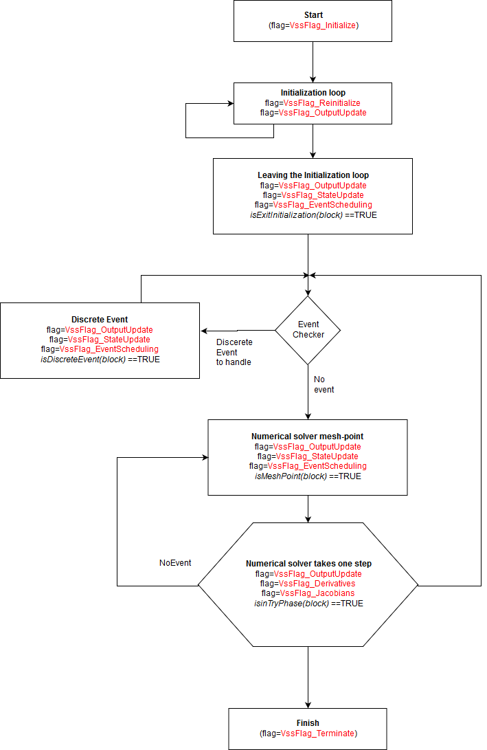
Flag Calling Sequence in Blocks
Data Types Supported in Blocks
Signals in Twin Activate can be matrices of various data types. The data type of input and output of a block may either be defined and fixed by the block or be inherited from the data type of other connecting blocks.
- SCSREAL_N: double data type ID
- SCSCOMPLEX_N: complex data type ID
- SCSINT32_N: int32 data type ID
- SCSINT16_N: int16 data type ID
- SCSINT8_N: int8 data type ID
- SCSUINT32_N: unsigned int32 data type ID
- SCSUINT16_N: unsigned int16 data type ID
- SCSUINT8_N: unsigned int8 data type ID
- SCSBOOL_N: Boolean data type ID
- SCSSTRING_N: string data type ID
- SCSREAL_COP: double data type
- SCSCOMPLEX_COP: complex data type
- SCSINT32_COP: int32 data type
- SCSINT16_COP: int16 data type
- SCSINT8_COP: int8 data type
- SCSUINT32_COP: unsigned int32 data type
- SCSUINT16_COP: unsigned int16 data type
- SCSUINT8_COP: unsigned int8 data type
- SCSBOOL_COP: Boolean data type
- SCSSTRING_COP: string data type
You are encouraged to use these data types instead of directly using C data types in the definition of simulation functions.
Feedthrough Information in Blocks
The feedthrough is a block property that specifies the input-output dependency of the block. This property must be specified when a new block is constructed (including for blocks realized by custom blocks). Specifically, the feedthrough property is a vector of size equal to the number of block inputs.
In this case, the output y does not directly depend on the input u. The integrator block (its input in particular) does not have the feedthrough property. The feedthrough property should be provided correctly otherwise the Twin Activate compiler cannot compute proper scheduling. A scheduling error might occur if a true feedthrough property is erroneously set to false. On the other hand, specifying a feedthrough property to be true when it is not can lead to a non-existing algebraic loop error detected by the compiler. The algebraic loop error occurs when the diagram contains a path looping through ports having all feedthrough properties. In that case, the blocks cannot be scheduled by the compiler. Even if there are ways to "break" algebraic loops (in particular using the Loopbreaker block), it is better not to introduce non-existing ones by properly defining the feedthrough properties of new blocks. For end users, learning about this property is useful for dealing with algebraic loop errors.
Examples
In this section, several examples are given in order to illustrate the way a simulation function is written.
Simplified Gain Block
#include "vss_block4.h"

VSS_EXPORT void SimpleGainBlock (vss_block *block,int flag)
{
    if (flag==VssFlag_OutputUpdate){
        SCSREAL_COP *u=GetRealInPortPtrs(block,1);
        int ru=GetInPortRows(block,1);
        int cu=GetInPortCols(block,1);

        SCSREAL_COP *y=GetRealOutPortPtrs(block,1);
        int ry=GetOutPortRows(block,1);
        int cy=GetOutPortCols(block,1);

        SCSREAL_COP *Gain=GetRealOparPtrs (block,1);
        int rowGain=GetOparSize(block,1,1);
        int colGain=GetOparSize(block,1,2);
        int i, j, k;
        for (i=0;i<ry;++i){
            for (j=0;j<cy;++j){
                k=i+j*ry;
                y[k]=Gain[k]*u[k];
            }
        }
    }
}rowGain=GetOparSize(block,1,1);
colGain=GetOparSize(block,1,2);Simplified ODE/DAE Block
with initial value:
This ODE can be implemented as follows:
#include "vss_block4.h"

VSS_EXPORT void Simple_ODE_Block (vss_block *block, int flag)
{
    SCSREAL_COP *y=GetRealOutPortPtrs(block,1);
    SCSREAL_COP *xd=GetDerState(block);
    SCSREAL_COP *x=GetState(block);
    int nx=GetNstate(block);
    int i;

    switch(flag)
    {
        case VssFlag_Initialize:
            x[0]=1.0;
            x[1]=2.0;
            break;
        case VssFlag_OutputUpdate:
            for (i=0;i<nx;++i){
                y[i]=x[i];
            }
            break;
        case VssFlag_Derivatives:
            xd[0]=-x[0]+x[1]*x[0];
            xd[1]=-3*x[1]+2*x[0];
            break;
        default:
    }
}
In this code, first the pointers to state (x) and state derivative
(xd), as well as the size of the state (nx),
are obtained. Three flags are used, VssFlag_OutputUpdate for
output of the state value and VssFlag_Derivatives for returning
the time derivative of the state.
The C code for this DAE can be expressed as follows:
#include "vss_block4.h"

VSS_EXPORT void Simple_DAE_Block (vss_block *block, int flag)
{
    SCSREAL_COP *y=GetRealOutPortPtrs(block,1);
    SCSREAL_COP *xd=GetDerState(block);
    SCSREAL_COP *x=GetState(block);
    SCSREAL_COP *res=GetResState(block);
    int nx=GetNstate(block);
    int i;

    switch(flag)
    {
        case VssFlag_Initialize:
            x[0] =1.0;
            x[1] =2.0;
            xd[0]=0.0;
            xd[1]=0.0;
            break;

        case VssFlag_OutputUpdate:
            for (i=0;i<nx;++i){
                y[i]=x[i];
            }
            break;

        case VssFlag_Derivatives:
            res[0]=-xd[0]-x[0]+x[1]*x[0];
            res[1]=-xd[1]-3*x[1]+2*x[0];
            break;

        default:
    }
}
Simplified Counter (inc/dec) Block
This example develops a counter block. Whenever an event activates the counter, the counter increments or decrements its value. The initial value of the counter and the direction of the counter are given as block parameters.
#include "vss_block4.h"
VSS_EXPORT void Simple_counter_Block (vss_block *block, int flag)
{
    SCSINT8_COP *y=Getint8OutPortPtrs(block,1);
    SCSINT8_COP initial=*Getint8OparPtrs(block,1);
    SCSINT8_COP dir =*Getint8OparPtrs(block,2);
    SCSINT8_COP mem = Getint8OzPtrs(block,1);
    int nevprt = GetNevIn(block);

    if (flag==VssFlag_Initialize){
        mem[0]=initial;
    }else if (flag==VssFlag_OutputUpdate) {
        y[0]=mem[0];
    }else if (flag== VssFlag_StateUpdate) {
        if (nevprt ==1){
            if (dir==1)
                mem[0]++;
            else
                mem[0]--;
        }
    }
}
The initial value of the counter is returned by the macro
Getint8OparPtrs(block,1). The block needs storage to keep the
counter value. OZ storage was chosen, which is a scalar 8-bit
integer here. In general, OZ is initialized before the simulation
phase, but for demonstration purposes, it was reinitialized in
flag=VssFlag_Initialize. On every block activation with
flag=VssFlag_StateUpdate, the nevprt is
checked to verify if the activation is a discrete event. Then, based on the block
parameter (dir), the counter is incremented or decremented.
Simplified Counter Block with Overflow
In the above counter, suppose that the block needs to generate an event when the counter overflows/underflows. In this case, an event needs to be programmed in flag=VssFlag_EventScheduling.
#include "vss_block4.h"
VSS_EXPORT void Simple_counter_Block (vss_block *block, int flag)
{
    SCSINT8_COP *y=Getint8OutPortPtrs(block,1);
    SCSINT8_COP initial=*Getint8OparPtrs(block,1);
    SCSINT8_COP dir =*Getint8OparPtrs(block,2);
    SCSINT8_COP mem = Getint8OzPtrs(block,1);
    int nevprt = GetNevIn(block);
    double *evout= GetNevOutPtrs(block);

    if (flag==VssFlag_Initialize){
        mem[0]=initial;
    }else if (flag==VssFlag_OutputUpdate) {
        y[0]=mem[0];
    }else if (flag== VssFlag_StateUpdate) {
        if (nevprt ==1){
            if (dir==1)
                mem[0]++;
            else
                mem[0]--;
        }
    } else if (flag==VssFlag_EventScheduling){
        if (nevprt ==1){
            if (dir==1){
                if (mem[0]==127) {
                    evout[0]=0.0;
                }
            }else{
                if (mem[0]==-128){
                    evout[0]=0.0;
                }
            }
        }
    }
}
In this counter, when the block is called with flag=VssFlag_EventScheduling, the content of the counter is checked and, based on the counter direction and its value, an immediate discrete event (with zero delay) is generated at its first activation output port.
Simplified Bouncing Ball Block
In order to demonstrate the way zero-crossings and modes are handled, consider the model of a simple bouncing ball.
When the ball hits the ground, its vertical speed changes according to:
The code for modeling this system is:
#include "vss_block4.h"
VSS_EXPORT void Simple_BouncingBall_Block (vss_block *block, int flag)
    SCSREAL_COP *h=GetRealOutPortPtrs(block,1);
    SCSREAL_COP *v=GetRealOutPortPtrs(block,2);
    SCSREAL_COP *xd=GetDerState(block);
    SCSREAL_COP *x=GetState(block);
    SCSREAL_COP *g=GetGPtrs(block);
    int nevprt = GetNevIn(block);

    switch(flag)
    {
        case VssFlag_OutputUpdate:
            h[0]=x[0];
            v[0]=x[1];
            break;

        case VssFlag_Derivatives:
            xd[0]= x[1];
            xd[1]= -9.81 ;
            break;

        case VssFlag_StateUpdate:
            if (nevprt==-1){
                x[0]= 0.0;
                x[1]= -0.9*x[1];
            }
            break;

        case VssFlag_ZeroCrossings
            g[0]=x[0];
            break;

        default:
    }
}
The model contains two state variables, one for the height of the ball
(h) and another for the velocity of the ball
(v). The block has two output ports, the first outputs
h and the second, v. A zero-crossing
surface has been used to check whether the ball has hit the ground. Naturally, the
height of the ball (h) can be used as a zero-crossing surface in
the block. When the ball hits the ground, an internal event is generated (with
nevprt==-1). At this moment, the state variables
(h and v) are reset with new values.
Absolute Value Block
In order to demonstrate the way mode variables are handled in a block, consider a simplified version of the Abs block in Twin Activate. This block computes the absolute value of its input.
When a variable step-size numerical solver is chosen in Twin Activate, if the output of the Abs block affects the continuous-time state of the model, the mode variable should be used inside the block to correctly handle the non-smoothness or discontinuity. The absolute value block needs then a zero-crossing surface to detect when the input crosses zero and a mode to handle the discontinuity. The zero-crossing surface is defined in flag=VssFlag_ZeroCrossings. When the block is called with this flag, the block updates the zero-crossing surface and modes.
In order to update the mode variables, the areModesFixed(block) macro is checked. If false, modes can be updated. If the simulator calls the block with flag=VssFlag_OutputUpdate for updating the outputs, the block should make use of the mode variable. If the simulator calls the block when areModesFixed(block) is true, the outputs depends on the mode. The code for the simulation function of the block is:
#include <vss_block4.h>
VSS_EXPORT void simple_abs(vss_block *block,int flag)
{
    SCSREAL_COP *u=GetRealInPortPtrs(block,1);
    SCSREAL_COP *y=GetRealOutPortPtrs(block,1);
    SCSREAL_COP *g=GetGPtrs(block);
    SCSINT32_COP *mode=GetModePtrs(block);
    int side;

    switch(flag)
    {
    case VssFlag_OutputUpdate:
        if (areModesFixed(block)) {
            side=mode[0];
        }else {
            if (u[0]<0){ side=2;
            } else{ side=1;
            }
        }
        if (side==1){ y[0]=+u[0];
        } else{ y[0]=-u[0];
        }
        break;
    case VssFlag_ZeroCrossings:
        g[0]=u[0];
        if (!areModesFixed(block)) {
            if(g[0]<0){
                mode[0]=2;
            }else{
                mode[0]=1;
            }
        }
    }
}
A Block to Write Signals to a File
This example demonstrates the way the block input can be written into an ascii file. The input of the block is scalar of data type double. The code is:
#include "vss_block4.h"

typedef struct {
    unsigned int index;
    FILE *pFile;
}write2File_t;

#define WS ((write2File_t *) GetWorkPtrs(block))

VSS_EXPORT void write_to_file(vss_block *block,int flag)
{
    switch(flag)
    {
        /*---------------------------*/
    case VssFlag_Initialize:
        {
            char *fname=Getint8OparPtrs(block,1);
            GetWorkPtrs(block)= (write2File_t*)vss_malloc(block,
                sizeof(write2File_t) );
            if (!WS){SetBlockError(block,1);return;}
            WS->index=0;
            WS->pFile = fopen (fname,"w");
            if(!WS->pFile) {Coserror(block,"Unable to open the file %s\n"
                , fname); return;}
            fprintf (WS->pFile, "input data.....\n");
        }
        break;
        /*---------------------------*/
    case VssFlag_Terminate:
        {
        if (!WS) return;
        if (WS->pFile){
            fprintf (WS->pFile, "Number of lines: %d",WS->index);
            fclose(WS->pFile);
            }
        }
        break;
        /*---------------------------*/
    case VssFlag_OutputUpdate:
        {
            SCSREAL_COP *u = GetRealInPortPtrs(block,1);
            if (!isinTryPhase(block)){
                fprintf (WS->pFile, "%g\n", u[0]);
                WS->index++;
            }
        }
        break;
    }
    return;
}
At the beginning of the simulation, when the block write_to_file is called with flag = VssFlag_- Initialize, the file whose name (fname) is given as a block parameter is opened for writing. In order to dump the block input data into the file at block calls with flag = VssFlag_OutputUpdate, the pointer to file should be kept throughout the simulation. This pointer can either be stored as a static variable in the simulation function or in the block’s WorkSpace (accessible by macro GetWorkPtrs(block)). The static method is not recommended, since if two instances of this block are used in a model, both share the same static variable that perturbs the operation of the blocks. For this reason, you create a structure to keep the file pointer as well as any other variable that needs to be kept during the simulation. The structure is allocated with the vss_malloc function of Twin Activate. This function is similar to malloc, but with the difference that the pointer of the allocated memory is managed and freed by the Twin Activate simulator. You do not need to worry about freeing the memory at the end. Twin Activate also provides the function vss_file_open(block,fname,"w"); instead of fopen(fname,"w"). vss_file_open does not need fclose; it is done automatically by the simulator. Another important point in the above code is using isinTryPhase (block) macro. This macro filters the try calls where the input of the block is not a valid value and can be ignored.
Simplified ODE with Constraint Preservation
In some models, the states of the dynamic systems need to satisfy invariant or some algebraic relationships. This kind of invariant usually results from mass or energy conservation or other physical laws. If the ODE is integrated by standard numerical solvers, slight errors in the numerical solution are accumulated and cause the solutions to fail to satisfy the solution invariant exactly. In order to add these kinds of invariant to the ODE of the block, Twin Activate provides the use of flag =VssFlag_-Projection. and the CPODE solver. During the simulation, the simulator calls the simulation functions of the blocks with constraints with this flag and requests that the block compute the invariant or the projections as a function of newly computed states. This results in a solution that sticks to the constraints.
The following example is the standard pendulum model with two invariants. The dynamic model of the pendulum is:
The first invariant ensures that the length of the pendulum remains equal to L throughout the simulation.
The code for the simulation function of the pendulum model with constraint preservation is as follows:
#include "vss_block4.h"
#define g 9.81
VSS_EXPORT void CBlockFunction(vss_block *block,int flag)
{
    double *xd=GetDerState(block);
    double *X=GetState(block);
    double *y=GetRealOutPortPtrs(block,1);
    int nx=GetNstate(block);
    int i, ip;

    switch(flag)
    {
        /*---------------------------*/
    case VssFlag_Initialize:
        {
            SetConstraintKind(block,CONSTRAINT);
            SetNConstraint(block,2);
            X[0]=1;
            X[1]=X[2]=X[3]=0;
            return;
        }

    case VssFlag_Projection:
        {
            double x, y, xd, yd;
            double *corr=GetCorrPtr(block);
            x = X[0];
            y = X[1];
            xd = X[2];
            yd = X[3];

            corr[0]= x*x + y*y - 1.0;
            corr[1]= x*xd + y*yd;
            return;
        }
    case VssFlag_Derivatives:
        {
            double x, y, xd, yd, tmp;
            x = X[0];
            y = X[1];
            xd = X[2];
            yd = X[3];
            tmp = xd*xd + yd*yd - g*y;

            xd[0] = xd;
            xd[1] = yd;
            xd[2] = -x*tmp;
            xd[3] = -y*tmp - g;
            return;
        }

    case VssFlag_OutputUpdate:
        {
            for (i=0;i<nx;i++)
                y[i] = X[i];
            return;
        }
    default:
        return;
    }
}
ODE and DAE Blocks Providing Analytical Jacobian
The simulation function for this block providing the analytical Jacobian matrix is given below. In flag=VssFlag_-Initialize, the jacobian flag is set to 1 to inform the simulator that the block provides the analytical Jacobian. The J vector has been filled with the Jacobian entries in flag VssFlag_Jacobians. Note that the J matrix is filled column-wise.
#include "vss_block4.h"
VSS_EXPORT void Simple_ODE_Block (vss_block *block, int flag)
{
    SCSREAL_COP *y=GetRealOutPortPtrs(block,1);
    SCSREAL_COP *xd=GetDerState(block);
    SCSREAL_COP *x=GetState(block);
    SCSREAL_COP *J= GetJacobianPtrs(block);
    int nx=GetNstate(block);
    int i;

    switch(flag)
    {
        case VssFlag_Initialize:
            SetAjac(block,1);
            return;

        case VssFlag_OutputUpdate:
            for (i=0;i<nx;++i){
                y[i]=x[i];
            }
            break;

        case VssFlag_Derivatives:
            xd[0]=-x[0]+x[1]*x[0];
            xd[1]=-3*x[1]+2*x[0];
            break;

        case VssFlag_Jacobians:
            J[0]=-1+x[1];
            J[1]=2;
            J[2]=x[0];
            J[3]=-3;
            break;

        default:
    }
}
The Jacobian matrix for a DAE is a little different. For the DAE
the Jacobian Matrix is defined as follows:
where α (accessible by macro GetAlphaPt(block)) and β (accessible by macro GetBetaPt(block)) values are given by the simulator. As a result the Jacobian matrix for the above DAE will be:
#include "vss_block4.h"

VSS_EXPORT void Simple_ODE_Block (vss_block *block, int flag)
{
    SCSREAL_COP *y=GetRealOutPortPtrs(block,1);
    SCSREAL_COP *xd=GetDerState(block);
    SCSREAL_COP *x=GetState(block);
    SCSREAL_COP *J= GetJacobianPtrs(block);
    SCSREAL_COP *alpha=GetAlphaPt(block);
    SCSREAL_COP *beta =GetBetaPt(block);
    int nx=GetNstate(block);
    int i;

    switch(flag)
    {
        case VssFlag_Initialize:
            SetAjac(block,1);
            return;
        case VssFlag_OutputUpdate:
            for (i=0;i<nx;++i){
                y[i]=x[i];
            }
            break;
        case VssFlag_Derivatives:
            xd[0]=-x[0]+x[1]*x[0];
            xd[1]=-3*x[1]+2*x[0];
            break;
        case VssFlag_Jacobians:
            J[0]=-alpha[0]+alpha[0]*x[1]-beta[0];
            J[1]=-2*alpha[0] ;
            J[2]=alpha[1]*x[0];
            J[3]=-3*alpha[1]-beta[1];
            break;
        default:
    }
}
A Simple Block for Programming an Initial Event
Consider a simple block with one output event port that generates an event at a time instant specified by a block parameter. In order to generate the event, the block should read the parameter value using evtime= GetRealOparPtrs(block,1). Events are only programmed at flag== VssFlag_EventScheduling. In order to program this event only once, at the beginning of the simulation, the isExitInitialization(block) macro can be used. This macro indicates if the initialization has finished and the simulation is being started. The relative time with respect to the current simulation time and the desired event time is defined and set to the evout vector.
#include "vss_block4.h"

VSS_EXPORT void EventGenerateBlock(vss_block *block,int flag)
{
    double *evout =GetNevOutPtrs(block);
    double *evtime=GetRealOparPtrs(block,1);
    if(flag==VssFlag_EventScheduling){
        if (isExitInitialization(block)){
            evout[0]=evtime[0]-GetVssInitialTime(block);
        }
    }
}