
Tutorial: Basic Die Design
Tutorial Level: Beginner First, learn the basics of die design.
In this lesson, you will learn how to:
- Fill in holes using the Patch and Combine geometry tools.
- Define the part.
- Adjust draw direction.
- Define the symmetry plane.
- Create a flat binder from a new surface.
- Create the addendum.
- Create the draw die and adjust the radius of the fillet along the edge of the binder.
- Create a matching die by offset.
Change the Default Units
In Inspire Studio, the default unit for length is centimeters. In this tutorial, we'll be using millimeters for length.
- On the Help menu, click the Preferences button.
- In the Preferences window, click Inspire Studio > Units.
-
Under Current session units, change the
Length to mm.
For the other measurements, keep the default units.
- Click Apply.
- Click Save as Defaults.
- Click OK.
Import the File
- On the File menu, select Import.
-
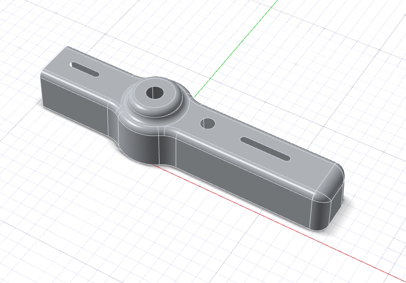
Browse to the die_module_part_1.x_b file.
The model is loaded.
Fill in the Holes
Let's fill in the holes using the Patch tool and then combine the patches with the rest of the model to create one object.
-
Fill in the holes:
On the ribbon, click the Surfaces tab.
-
Fill in the first hole:
- Click the Patch icon.

- Click an edge of the hole on the very left, and then right-click to confirm.
- In the guide bar, select Surface Tangency (G1) to fill the hole with a smooth, continuous patch without sharp edges at the seams.
- Right-click and mouse through the check mark to exit, or double-right-click.
- Click the Patch icon.
-
Fill in the second hole:
- Click the Patch icon.
- Click an edge of the next hole, and then right-click to confirm.
- In the guide bar, select Surface Tangency (G1).
- Right-click and mouse through the check mark to exit, or double-right-click.
- Click the Patch icon.
-
Fill in the third hole:
- Click the Patch icon.
- Click an edge of the next hole, and then right-click to confirm.
- In the guide bar, select Surface Tangency (G1).
- Right-click and mouse through the check mark to exit, or double-right-click.
- Click the Patch icon.
-
Fill in the fourth hole:
- Click the Patch icon.
- Click an edge of the hole on the very right, and then right-click to confirm.
- In the guide bar, keep the default option of Positional to connect the patch surface without tangency to the surface edge.
- Right-click and mouse through the check mark to exit, or double-right-click.
- Click the Patch icon.
-
Fill in the first hole:
-
Combine the patches with the rest of the model to create one object:
- On the ribbon, click the Modify tab.
-
Click the Combine icon.
- Select the model and the four holes. Right-click to confirm.
- Right-click and mouse through the check mark to exit, or double-right-click.
Define the Part
Select a part and define the thickness and position.
- On the ribbon, click the Die Design tab.
-
Click the Part icon.
-
Click the Assign icon.
- Select the part.
- Change the Thickness to 1.00 mm.
- By default, the part is designated as the Bottom Face of the thin solid. In this tutorial, we'll keep the default setting.
- Right-click and mouse through the check mark to exit, or double-right-click.
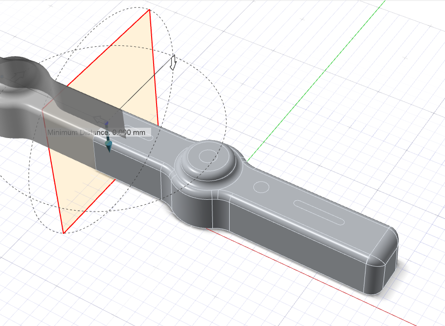
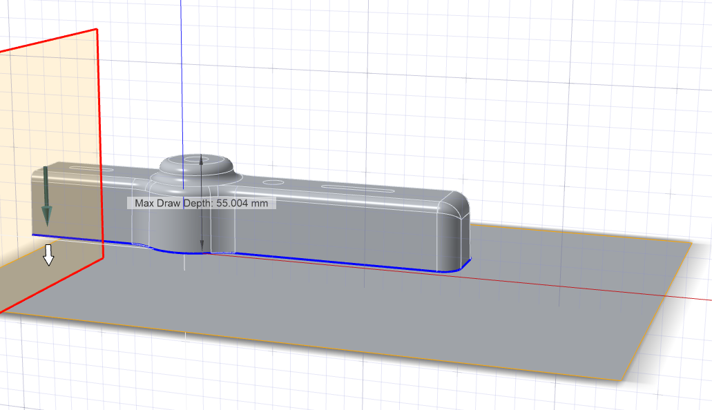
Set the Draw Direction
Adjust the draw direction to minimize the depth.
-
Click the Draw Direction icon.
-
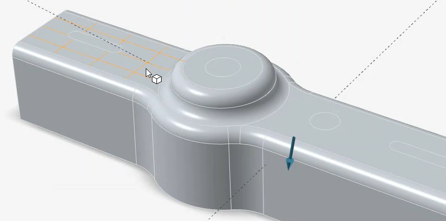
Set the draw direction:
-
In the guide bar, select Reference Geometry
 .
.
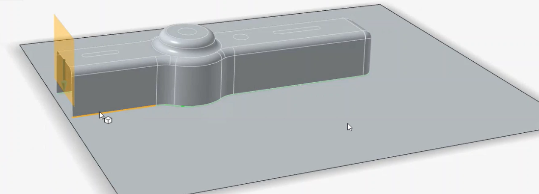
-
In the modeling window, select the face displayed in yellow below as
the reference geometry.
-
In the guide bar, select Reference Geometry
- Right-click and mouse through the check mark to exit, or double-right-click.
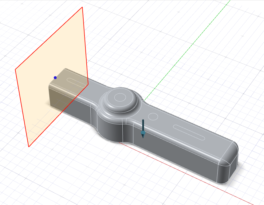
Define the Symmetry Plane
-
Click the Symmetry icon.

A blue arrow is displayed with an origin point.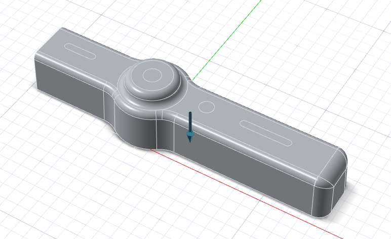
-
Hover over a part to position the symmetry plane, and then click to create the
symmetric copy.
- Right-click and mouse through the check mark to exit, or double-right-click.
Create the Binder
Define a binder for the draw die. In this tutorial, we'll create a flat binder from a new surface.
-
Click the Binder icon.
-
Click the Create Flat icon.
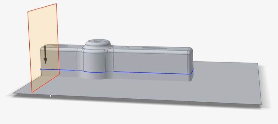
-
Click the addendum start edge at the bottom of the model.
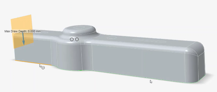
Because Chain selection is the default selection method, all connected edges are selected automatically and now displayed in dark blue. -
To create the flat binder, right-click.
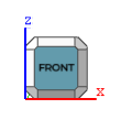
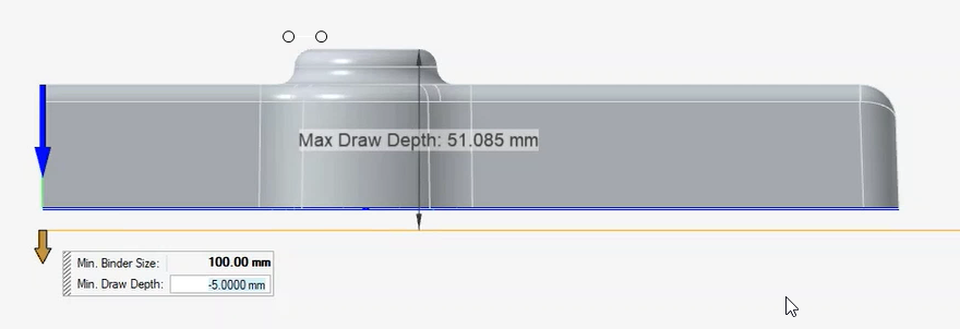
-
At the bottom left of the modeling window, click the
Front face of the View Cube to rotate to the front
view.
-
Enter a Min. Draw Depth of 5.00
cm to change the distance between the part and binder.
- Right-click and mouse through the check mark to exit, or double-right-click.
Create the Addendum
Let's create the addendum surface with the Loft tool.
-
Click the Addendum Loft icon.
-
Click the Loft icon.
-
By default, Chain selection is selected. Switch to
Tangent Selection. Select the addendum start edge
displayed in yellow below to select the entire chain.
Note: The binder for the addendum is implicitly assigned from the selected edges. - In the guide bar, for the rib type, choose Straight Line to create ribs that extend from the part with a line, ensuring tangent continuity, and are continuous down to the binder.
-
In the Control Panel, change the Surface Options: Creation method to
Sweep.
The addendum surface is created.
-
In the Control Panel, turn on Draft analysis, and then
rotate the model and zoom in as needed to check for negative draft. You should
see no issues.
- Right-click and mouse through the check mark to exit, or double-right-click.
Create the Draw Die
Create the draw die and adjust the radius of the fillet along the edge of the binder.
-
Click the Die icon.

-
Click the Die icon.
-
Select the flat binder.
To confirm your selection, right-click.
-
In the guide bar, the selection has changed to Addendum
and the Addendum Loft has been preselected.
Right-click to confirm.
- Select the radius manipular, then change the Radius to 4.0 mm.
- Right-click and mouse through the check mark to exit, or double-right-click.
Create a Matching Die
Create a matching die by offset.
-
Click the Matching Die icon.

- Select the die.
- In the guide bar, change the offset type to PS Offset.
- Right-click and mouse through the check mark to exit, or double-right-click.