Tutorial: Loft Addendum and Bridge
Learn to build and repair addendum surfaces using the Loft addendum tool and the Bridge tool.
- Add multiple addendum surfaces using Tangent Selection
- Propagate the addendum surface by using the Auto create rib locations and Addendum configuration options
- Bridge gaps between addendum surfaces
Import the File
-
Browse to the bpillar_mod_w_mod_binder.x_b file.
The model is loaded.
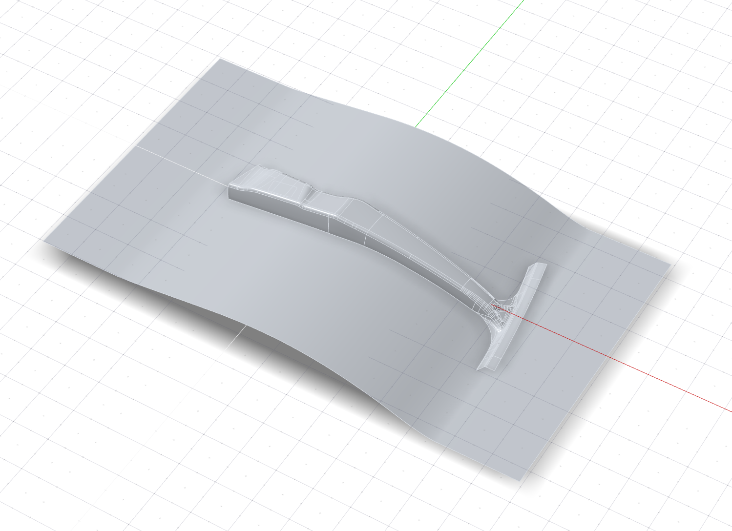
Define the Part
Select a part and define the thickness and position.
- On the ribbon, click the Die Design tab.
-
Click the Part icon.
-
Click the Assign icon.
-
Select the part, shown below in yellow.
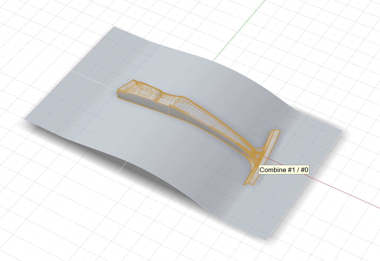
- Leave the Thickness at 0.120 cm.
- By default, the part is designated as the Bottom Face of the thin solid. In this tutorial, we'll keep the default setting.
- Right-click and mouse through the check mark to exit, or double-right-click.
Set the Draw Direction
Adjust the draw direction to minimize the depth and avoid negative drafts with the help of the Depth Box and Draft Analysis.
-
Click the Draw Direction icon.
-
To display the draw depth, in the guide bar, select Depth
Box.

- To display severe negative drafts in red and marginal negative drafts in yellow, select Draft Analysis.
-
Set the draw direction:
-
Click the Phi Angle arrow.
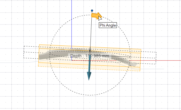
- Enter an angle of -3.0 deg.
-
Click the Phi Angle arrow.
- Right-click and mouse through the check mark to exit, or double-right-click.
Create the Binder
Define a binder for the draw die. In this tutorial, we'll assign an existing surface as the binder.
-
Click the Binder icon.
-
Click the Assign icon.
-
Selectable edges are green. Click one of these addendum start edges.
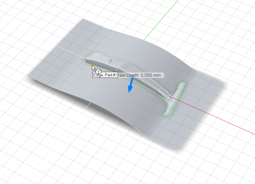
Because Chain selection is the default selection method, all connected edges are selected automatically and now displayed in dark blue.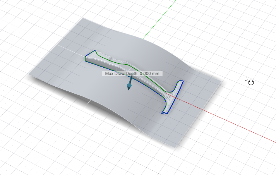 Note: By default, the Max Draw Depth (the maximum distance between the part and binder) is displayed.
 -
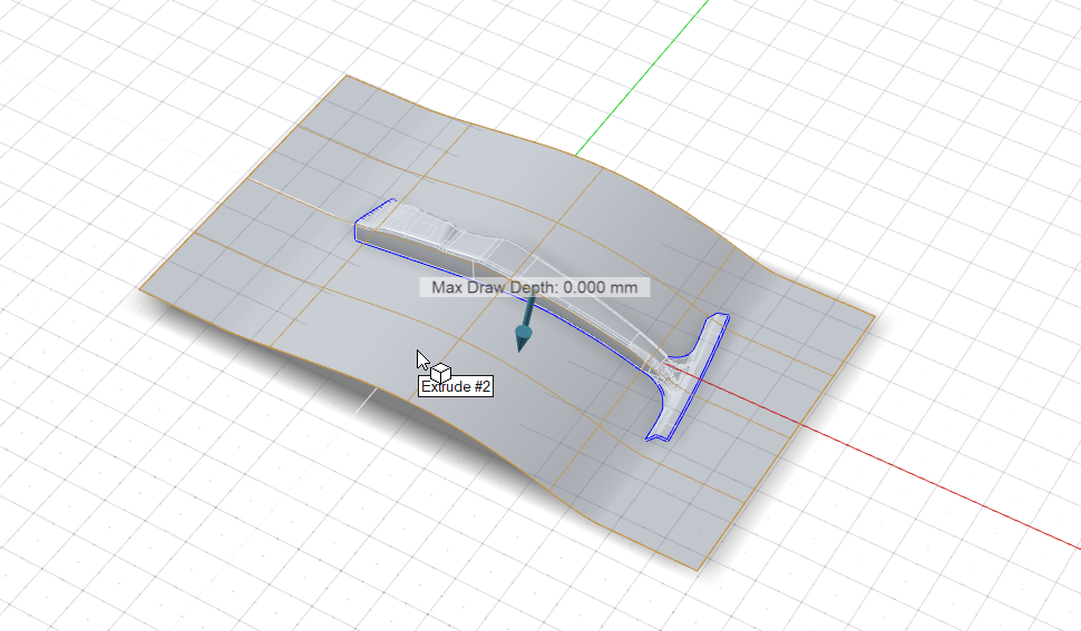
Assign the binder:
- In the guide bar, select Binder.
- Select the surface (Extrude #2), outlined in yellow below.
Create the Addendum
Let's create multiple addendum surfaces with the Loft tool using the Tangent selection option, and then propagate them using the Auto create rib locations and Addendum configuration options.
-
Click the Addendum icon.
Addendum Surface #1
-
Create the first addendum surface:
-
Click the Loft icon.
-
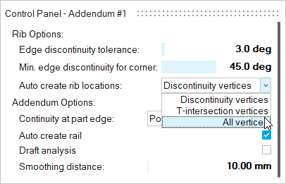
In the Control Panel, for Auto create rib
locations, select All Vertices.
Ribs will be automatically created at all vertices, points, and
locations on the part edge. This includes vertices on the edge,
T-intersection vertices, and discontinuity vertices.
Video 1: Create Addendum Surface #1
-
Click the Loft icon.
Addendum Surface #2
-
Create the second addendum surface:
-
Click the Loft icon.
-
In the Control Panel, for Auto create rib
locations, select All
Vertices.
-
Click the Loft icon.
Addendum Surface #3
-
Create the third addendum surface:
-
Click the Loft icon.
-
In the Control Panel, for Auto create rib
locations, select All
Vertices.
-
Click the Loft icon.
Addendum Surface #4
-
Create the fourth addendum surface:
-
Click the Loft icon.
-
In the Control Panel, for Auto create rib
locations, select T-intersection
vertices. This includes T-intersection vertices and
discontinuity vertices.
-
Click the Loft icon.
Addendum Surface #5
-
Create the fifth addendum surface:
-
Click the Loft icon.
-
In the guide bar, select Addendum Start Edges.
Then select the addendum start edges shown in the video.
Note: To reselect the addendum start edges, in the guide bar, select Clear Selection
 , and then select different addendum
start edges.
, and then select different addendum
start edges. -
In the Control Panel, for Auto create rib
locations, select All
Vertices.
-
Click the Loft icon.
Addendum Surface #6
-
Create the sixth addendum surface:
-
Click the Loft icon.
-
In the Control Panel, for Auto create rib
locations, select All Vertices.
Ribs will be automatically created at all vertices, points, and
locations on the part edge. This includes vertices on the edge,
T-intersection vertices, and discontinuity vertices.
-
Click the Loft icon.
Bridge Gaps Between Addendum Surfaces
Now we'll bridge gaps between the addendum surfaces with the Bridge tool and adjust them using the Constrain and Shape Factor options.
Gap #1
-
Bridge the first gap and fine-tune the shape:
-
Click the Bridge icon.

Video 1: Bridge Gap #1
-
Click the Bridge icon.
Gap #2
-
Bridge the second gap and fine-tune the shape:
-
Click the Bridge icon.
-
In the guide bar, Rib 1 is automatically
selected. Leave the selection method as Chain
selection. Select the first rib. Right-click to
confirm.
Note: To reselect the first rib, in the guide bar, next to Rib 1, select Clear Selection, and then select a different first
rib.
Video 2: Bridge Gap #2
-
Click the Bridge icon.
Gap #3
-
Bridge the third gap and fine-tune the shape:
-
Click the Bridge icon.
Video 3: Bridge Gap #3
-
Click the Bridge icon.
Gap #4
-
Bridge the fourth gap and fine-tune the shape:
-
Click the Bridge icon.
Video 4: Bridge Gap #4
-
Click the Bridge icon.
Gap #5
-
Bridge the fifth gap and fine-tune the shape:
-
Click the Bridge icon.
Video 5: Bridge Gap #5
-
Click the Bridge icon.
Gap #6
-
Bridge the last gap and fine-tune the shape:
-
Click the Bridge icon.
Video 6: Bridge Gap #6
-
Click the Bridge icon.
Create the Draw Die
Create the draw die and adjust the radius of the fillet along the edge of the binder.
-
Click the Die icon.

-
Click the Die subtool.
Create a Matching Die
Create a matching die by offset.
-
Click the Matching Die icon.

- Select the die as shown in this video.
- Right-click and mouse through the check mark to exit, or double-right-click.