Set the default reference area for the Top
and Bottom sides.
Display Option
Set the detailed settings of the display.
Board Display
Reference Designator: Select whether to display the component.
Pin: Select whether to display the component pin (pad).
Pattern: Select whether to display the route.
Silk: Select whether to display the silkscreen.
Except Component: Exclude Reference, Part, or Package components
from the display by clicking ... to open the
String Filter Set Up dialog.
In the example above, the component, which includes TP in the part
name, is excluded.
Pin Display
First Pin: Mark the first pin position.
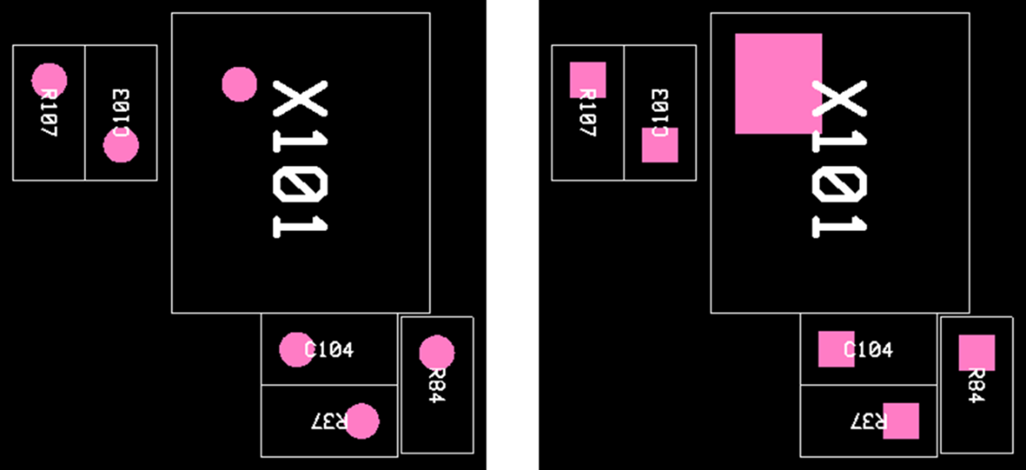
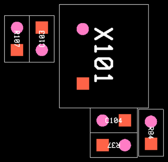
First Pin-Pad Max Area: The first pin pad is marked with a pink
solid rectangle. If not selected, it displays as shown in the left
picture. Figure 1.
Second Pin: Mark the second pin location. Figure 2.
Pin PAD Scale: Set the marking size of the first and second
pins.
Fit Text to Area: Display the positions of the pin number one and
two inside of the text area. This option only works for the two-pin
part.
Pin MaxMin: Display the pad area as a rectangle
shape.
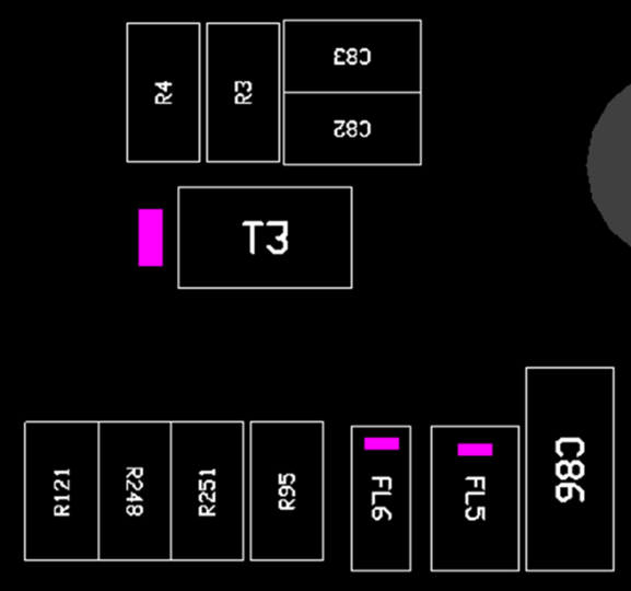
Polarity
Display the polarity mark for the polarized parts which can be set in the Polarity
item (refer to Polarity). Figure 3.
Name
and Property Display
Reference Name: Select whether to display the reference name.
Part Name: Select whether to display the part name.
Property Selection: Select whether to display the property
information.
Part Comment: Select a part property to display.
Reference Comment: Select a reference property to display.
Default
Text Option
Maximum Text Size: Display at the maximum size in the test
area.
Display Text Area: Display the text area as a rectangle shape.
Text area definition: Define the text area as a pad or COC
area.
Default Text Height: Set the text size. It will not exceed the text
area.
User
Comp Data: Select whether to display the user comp data set in Other
menu.
User
Comment: Select whether to display the user comment setting in Other
menu.
Upright
Reading: Display the text direction according to the ratio of the text area.
If the proportion of the text area is larger in the horizontal direction,
the text is displayed in the left to right direction. In case of a large
vertical direction, the text is displayed from bottom to top.
Mechanical Component (No Pin): Select whether to display the parts without
pin information such as a fiducial mark or a screw hole.
Auto
Zoom: Automatic zoom-in on the target part when you select a part in the
reference list.
Display
CAP Setting File Name to PDF: Export the Component Arrangement Plan setting
file name when printing a PDF file.
Display
CAD file created date.
Color Option
Define the color of each option.
Click
the empty field next to any Item to open the Select
Color dialog.
Select
a color, and then click OK.
Tool Option
Reference List: Select whether to display the reference list dialog on the
right side of the screen.
Display
Option: Select whether to display the display option dialog on the right
side of the screen.
Label
Display: Select whether to display the label on upper right side of the
screen.
Label
Title: A list of labels that appear on the label. You can edit the title by
clicking Add or Delete.
Layer Option
Top
Layer: When displaying the top side, select the artwork layer to be
displayed.
Bottom
Layer: When displaying the bottom side, select the artwork layer to be
displayed.
Display
Text on Selected Layer to PDF: Option to include the part’s text of the
selected artwork layer when printing a PDF.
EBOM Link Option
Specify the *.ebi file set in the PollEx BOM. Refer to BOM to
learn how to create the *.ebi file.
Export Boundary to PDF
PCB
Outline: Export based on the PCB outline area.
Component: Export including the part area placed on the PCB.
Board
Figure (Drill): Export including the figure object area placed on the
PCB.
Pin Display Settings
Define pin settings.
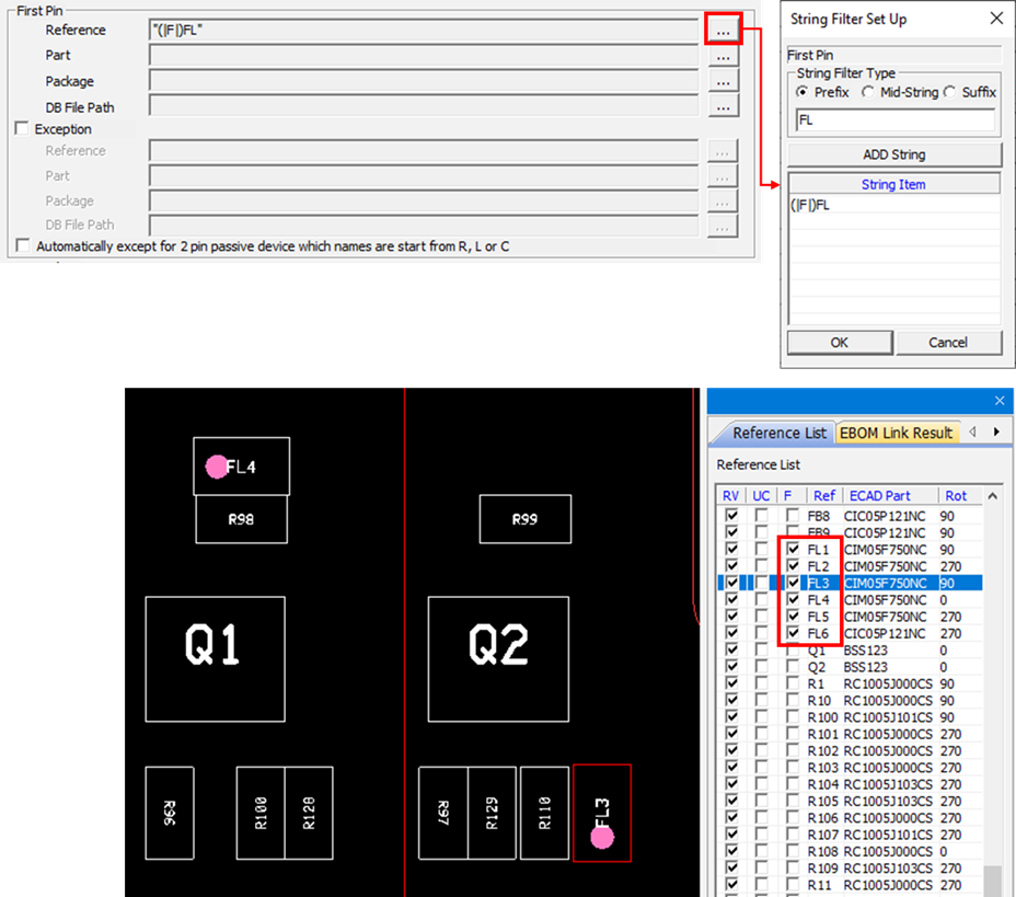
First pin: you can set whether to display the first pin and set the parts to display
in the String Filter dialog based on the reference, part and package names. For
example, when selecting the Prefix and entering FL in the string filter dialog, all
first pins of the reference name starting with the string FL are selected in the
reference list, as shown below. Figure 4.
Exception:
Select a part that excludes the first pin marking.
Automatically except for 2pin passive device which names are start from R,
L, or C: Exclude the two-pin passive device automatically, which starts with
R, L, and C.
Second Pin: You can set whether to display the second pin and setting the same
as the first pin.
User-Defined Pin
This menu is used when directly specifying the marking position of the first pin.
Table
Filter Type: Specify the filter type as either DB file or part
name.
Filter/DB File Path: Specify the filter condition or part DB file
path by double-clicking the column.
Pin Name: Specify the pin name to display as the first pin.
Add: Add a
new item to the table.
Delete:
Delete a selected item from the table.
Edit DB:
Edit a selected DB file by running the Edit Component DB. Refer to the
[Appendix] Edit Component DB in this manual.
Other
Define property, user comment, and user comp data settings.
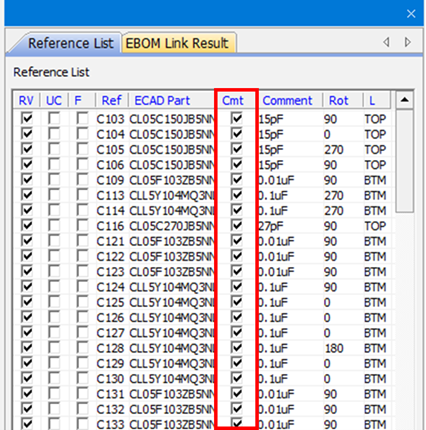
Property
You can set whether to check the comment (Cmt) column in the reference list according
to the criteria of the width, height, and component bound. Figure 5.
Example
1) Check parts with size (width and height) over one by selecting
Upper Bound.
Example
2) Check parts with size (width and height)) less than one by selecting
Lower Bound.
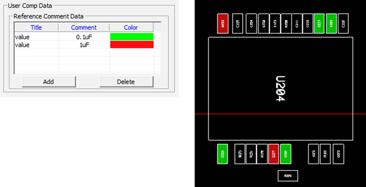
User Comp Data
This function highlights and displays the part to the user-defined color that matches
with the entered property information and the value. For example, if a part with a
value of 0.1uF is displayed in green, enter a value for the Title (case
insensitive), 0.1uF for the Comment, set the color in green, and click Apply. Figure 6.
Component Group Color
A component group can be specified to the user-defined color through the information
of the reference name and part name. In addition, part information and user-defined
comments can be displayed.
Select
Type of Component Group: Select a type to define a component group among
Reference Name, Part Name, Package Name, and Component DB.
Component Group Content: Set the string filter for defining the component
group.
In the
above example, parts starting with the reference name C are in a component
group.
When you
select the Select Type of Component Group as DB, you can load a pre-defined
component DB file from your computer. For more detailed information on how
to create or edit a DB file, refer to Appendix Edit Component DB in this
manual.
Property: Display the property information of the selected component group.
Default Comment: Enter the title of the property information to be
displayed.
Alternative Comment: To display the alternative component
information, select the title of the property.
Display Component List from User Selected Property: Create a list
based on the property value and directly select whether to highlight
the component.
Visible Property in Component: Display the property value specified
in the component area.
Fill:
Define the highlight color of the component.
Display
User Comment: Select whether to display the comment for the specified
component group.
EBOM Link
Define the display option for components in PCB.
Display Option for Component in PCB
Display X
Mark: Display the X mark for the parts that exist only in the PCB data in
the Display Value Properties. When Fill Color is activated, you can control
the On/Off of the X mark in the list. • Display Exception: Exclude the
component to display the X mark by using the string filter.
Polarity
Define the polarized component settings.
First Pin
First Pin: Display the polarity mark by designating the part that shows the polarity
at the first pin. You can set the parts to display in the string filter dialog based
on the reference, part, and package names. For example, when entering FL after
selecting Prefix in the string filter dialog, the polarity mark displays at the
first pin of the reference name that starts with FL (case
insensitive).
Second Pin
Second Pin: Display the polarity mark by designating the part that shows
the polarity at the second pin. You can set the parts to display in the
string filter dialog based on the reference, part, and package names.
User Defined Polarity Marking
For the parts marked with polarity at the specific location, the marking shape,
location, and target components can be set directly.
Marking Type: Select the shape of the polarity mark.
Point: Display the polarity mark in dot. Marking position is
selected among Left Top, Left Bottom, Right Top, Right Bottom, Top,
Bottom, Left, Right, First Pin, or Second Pin.
Bar: Display the polarity mark in bold lines. Marking position is
selected among Top, Bottom, Left, Right, First Pin, or Second
Pin.
Arrow: Display the polarity mark in arrows. Marking position is
selected either Left or Right.
Position: Select where the polarity mark is placed. Marking position varies
depending on the marking type.
Filter Type: Set the filter type to designate the component group to
display the polarity mark, which is selected among reference, part, package,
or DB file.
Filter/DB File Path: If the filter type is reference, part, or package, you
can select the part having the specified string through the string filter
function. If the filter type is DB file, you can select the pre-defined
component DB file. For more detailed information how to create or edit a DB
file, refer to [Appendix] Edit Component DB in this manual.