Annex 1: Creating a Reflectarray Database
This chapter summarizes the main steps for generating a database in order to build and analyze reflectarray/transmit array structure.
Step 1: Set the variable parameters for the structure. Select "Geometry --> Parameters --> Define Parameters" option on the menu bar. On this tab, all the parameters used in the construction of geometry will be set, see Define Parameters.
Step 2: Build the geometry for the elementary cell of the reflectarray / transmitarray structure. For this purpose the user can use all options available to construct geometries (see Geometry Menu) only with the following restrictions:
- The used geometries must be planar geometries.
- The geometries must be built in parallel planes to the XY plane (floor).
- If the user wants to leave some empty interfaces on the cell, a point for each empty interface must be added to detect an interface on the cell editor tab .
- The used geometries must be created with some parameters in order to have different cells.
This is an example of a cell geometries, where two elements has been added at the same interface, and a point has been inserted below to set the thickness of the material:

Note: Only first parameter (called 'len') has been defined, and the next ones are auxiliary parameters that depends directly on the first one. The auxiliary parameters are automatically defined when an operation is performed on an existing parameter, and their name starts always with the '$' character to be identified.
Step 3: Build the elementary cell of the structure. Select "Cell --> Define Cell" option on the menu bar. On this tab the parameters as layer material, cell size, cell replication, cell type (reflectarray or transmitarray) or skew angle will be configured.
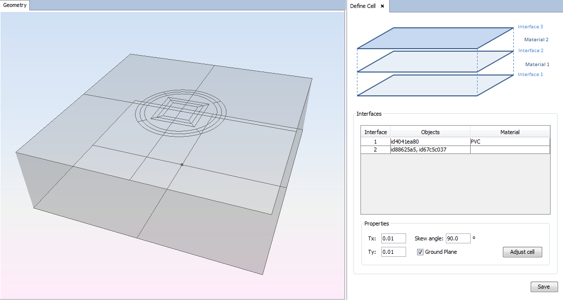
The example has two interfaces, defined by the two geometries added on the previous step. The materials for the layers are defined as the image shows, this is one material for each interface except on the top interface.
Step 4: Set simulation parameters. On this tab the values for the frequency, planewave and observation direction will be configured. For database creation is recommended to select only one frequency and if the cell geometry is not symmetric for the vertical and horizontal polarizations select asymmetric polarization type to analyze both polarizations.

Step 5: Meshing the periodical cell structure. Select "Meshing --> Create Mesh" option on menu bar. Parameters as divisions per wavelength, frequency and number of processors will be configured.

Step 6: Analyze the periodical cell structure. Select "Calculate --> Execute" option on menu bar.
Step 7: Select "Show Results --> Export Database".

Step 8: Show results. Select "Show Results --> View Cuts by Step".
