Multi-Filar Helix
This section explains how to create a multi-filar helix.
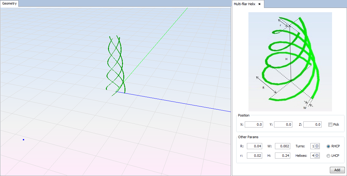
When the option is selected, the next panel and a previsualization of the antenna with the parameters on the panel are displayed.
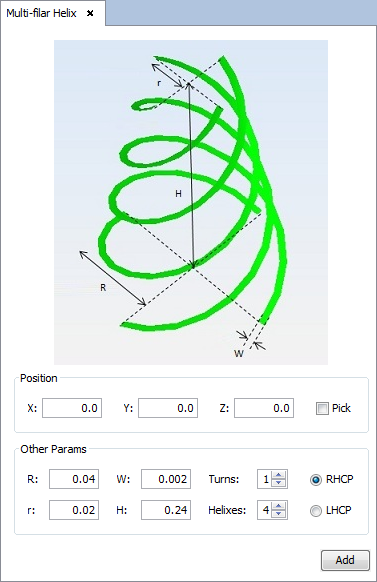
- Position: set the Cartesian coordinates for the position of the antenna. For the antenna, the user can select the position with the mouse, selecting the 'Pick' check box and clicking any point in the geometry panel.
- Other Params: set the value for the bottom radius (R), top radius (r) and height for the helix. The width of the strip (w), the number of turns (Turns) and the number of strips (Helixes) will be defined too. RHCP or LCHP selected option will define the polarization and the turn direction.
For each modification on parameters panel, this previsualization will be updated for the new parameters.
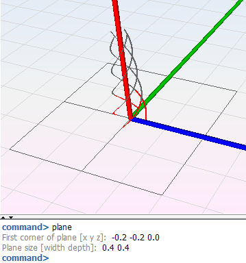
Clicking on the 'Add' button, the final visualization for the antenna with a red dashed line for the coaxial feed will be shown.
Note that this antenna should be placed on a metallic ground plane to provide a good performance as shown in the below figure. The ground plane surface must be attached below the antenna, with no gap between them.