
Preferences: Inspire
Define preferences for mouse controls and options related to how information is calculated and displayed.
What's New
| Preference | Description |
|---|---|
| Show What's New dialog at startup | Select the checkbox to display a What's New dialog when the application starts. What's New highlights new features. |
CAD Import Translator
Choose between a CT or Spatial reader.
By default, CATIA and STEP models use the Spatial reader because those file formats generally work best with Spatial. However, the quality of the translation is model-dependent. If you find your model is not reading cleanly into Inspire, please switch the translator in the preferences and reimport the model.
| Preference | Description |
|---|---|
| ACIS (.sab, .sat) | The default reader is CT. |
| CATIA V4 (.model) | The default reader is Spatial. |
| CATIA V5 (.CATPart, .CATProduct) | The default reader is Spatial. |
| IGES (.iges, .igs) | The default reader is CT. |
| Inventor (.ipt, .iam) | The default reader is CT. |
| PTC Creo (.asm, .prt) | The default reader is CT. |
| UG NX (Unigraphics) (.prt) | The default reader is CT. |
| SolidWorks (.sldprt, .sldasm) | The default reader is CT. |
| STEP (.step, .stp) | The default reader is Spatial. |
Geometry
| Preference | Description |
|---|---|
| Surface | Thickness: Define the default thickness used when creating surfaces. |
| Fillets | Radius: Define the default radius used when creating fillets. |
| Chamfers | Distance Angle: Define the default distance and angle
used when creating chamfers. Distance Distance: Define the default distance 1 and distance 2 values used when creating chamfers. |
| Part Replace | Auto Position: If Auto Position is enabled when doing part replacement, Inspire reads the internal transformation of the part within the CAD file to position the part within an assembly. If this option is turned off, it reads the part in where the part was created, generally (0,0,0). |
| Partition | Default Offset: Define the default offset used when creating partitions. |
| Parts | Select to maintain part orientation when moving to a new assembly. |
| Autofind | Select to automatically find features upon entering tools. |
| STL |
Export format: Select either ASCII or Binary as the export format for STL files. Export subdivision quality: Increase the level to create more triangles by splitting existing ones, maintaining the original geometry. |
| OBJ |
Import Format: Select whether to convert to PolyNURBS or mesh when importing OBJ files. |
| Import from CAD File | Fastest import:
Import hidden parts: Select Yes to import hidden parts that exist in some CAD formats like Catia V5. Note that importing hidden parts makes the import slower. Healing: When importing a CAD model, choose
how the application repairs geometry issues. Note: Healing
is not available when the Fastest import options,
Without diagnostics and With
diagnostics are turned on.
Split cylindrical faces: Enable this option to trim CAD cylinders on import. Combine points: Enable this option to combine points on import. Parasolid:
|
| Save to CAD format | Ignore deactivated parts: When saving a model as a
Parasolid, IGES, STEP, ACIS (.sat, .sab), STL, VRML, or Evolve (.pn) file, use
this option to indicate whether to include parts that have been deactivated. This
setting does not have an impact when saving as Inspire Mold .imod
files. Save parts in current positions: Select the checkbox to save parts in their current positions without maintaining transformations relative to the assembly. This simplifies the model structure when you import the data into your CAD system. Parasolid export version: Select the version of Parasolid that Inspire exports to. By default, files are currently exported to 28.1. Default export format for Save Selected: Select the format to use when using the Save Selected command. Parasolid: Export tags: Enable this option to include tags when exporting Parasolid files. For more information, see Tags. |
| SimSolid: Face Faceting Parameters |
SimSolid uses lightweight facets to represent part faces. Assembly, part names, and hierarchy are retained. Default facet settings should be sufficient for most geometries, but adjustments can be made. The following faceting parameters are used to control tessellation:
|
| PDM (Product Data Management) | Select the check box to Check for updated parts at a regular interval as specified in the Timer (minutes) field. |
Implicit
| Preference | Description |
|---|---|
| Use GPU | Select the checkbox to use the computer's GPU (graphics processing unit) for implicit modeling. When the checkbox is not selected, calculations are performed on the CPU. |
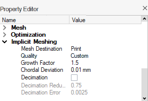
| Use Adaptive Remeshing |
When converting implicit parts to a mesh representation with one of the
remeshing options, a new remeshing algorithm has been implemented to create
adaptive meshes where the element size remains small near features and larger on
flatter regions.
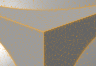 When the checkbox is enabled, the Growth Factor and
Chordal Deviation controls are available in the
Property Editor to control how remeshing is performed:
 |
Mouse Controls
| Preference | Description |
|---|---|
| Zoom Speed | Use to change the speed when zooming with the mouse. |
| Presets | This option defines the pan, view, and rotate controls assigned to the left
and right mouse buttons, so they are the same as used in another
application. Presets mouse controls for Inspire can be edited. To restore the preset values, click Use Defaults in the lower left corner of the Preferences window. |
Visualization
| Preference | Description |
|---|---|
| Visualization | Tessellation edge deviation: The maximum distance
allowed between the edge and the geometry used to approximate it for rendering. A
smaller deviation will result in better graphical quality but slower system
performance. Tessellation surface deviation: The maximum distance allowed between the surface and the geometry used to approximate it for rendering. A smaller deviation will result in better graphical quality but slower system performance. Enable fading effects: Select this option to make a part slowly fade away when you hide it. We recommend that you deselect this option when working with large assemblies to improve performance. Show section cuts in part color: Show section cuts in the same color as the parts. Load labels: Select which constraint types
are visible in the modeling window.
|
| View Cube | Show view cube: Define when the View Cube is visible
in the modeling window. Position: Define the position of
the View Cube in the modeling window.
Show axis arrows: Display the x-, y-, and z-axes on the View Cube. Geometry: Define the View
Cube's shape.
Show View Cube rotators: Define when the View
Cube rotators are visible in the modeling window.
Show View Cube reflectors: Define when the
View Cube reflectors are visible in the modeling window.
Increment angle: Define by how many degrees left- and right-clicking the arrows incrementally rotates the view. By default, left- and right-clicking increments by + and - 15 degrees. |
Mass Calculation
| Preference | Description |
|---|---|
| Mass calculation | Right-click the column header in the Model Browser and select Mass to view masses. To improve overall performance, when a CAD file is imported the mass sizes are not calculated and are shown as ** in the Model Browser. Click the Calculate button to display the mass. |
Move Tool
| Preference | Description |
|---|---|
| Free Move: Show angles when editing tool position | By default only the X, Y, Z coordinates of the Move tool origin are shown in the microdialog. If this preference is selected, the angles are shown as well when editing the tool position. |
Collision Detection
| Preference | Description |
|---|---|
| Check for collisions | Define whether Inspire Mold should check for collisions between all parts, no parts, or only parts that specifically have collision detection applied. |