
Mold
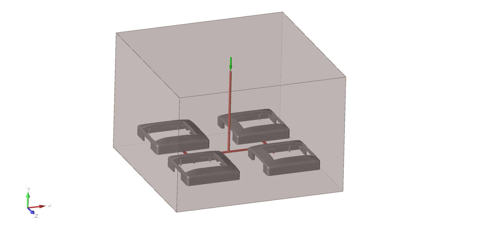
Use the Mold tool to generate a mold that contains the part, runner system, and any other components.
Location: Molding tab, Tooling secondary ribbon
Add/Edit Mold
Create and edit a mold that contains the model parts and runner system.
-
Click the Tool icon.

-
Click the Add/Edit Mold icon.

Inspire Mold creates a mold that is by default large enough to contain the part and any runner system components.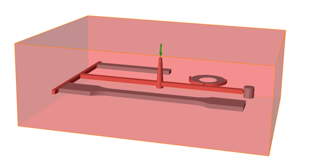
-
Use the microdialog options to adjust the margins and define the position,
material, temperature, and dimensions of the mold.

Microdialog Options
Define the material, temperature, and position of the mold.
| Option | Description |
|---|---|
| Select the Material Viewer to examine the material's
Thermal, Rheological, Mechanical, PVT and Fiber properties. Note: You can use the
Material Viewer to edit an existing material, save it with
a new name, and access it from the My Materials
tab. |
|
 |
Select a material from the list. |
 |
Enter the temperature of the material. |
| Select the Move tool to position the mold. | |
 |
Select the Reset button to apply the default parameters to the mold. |
 |
Select the Move Mold Face tool, then select the mold face that you want to move. By default, the filling system inlet will be even with the surface of the mold . |
 |
Enter the dimensions of the mold in the X-, Y- or Z- direction. |
 |
Position a mold face on the X-, Y- or Z-axis. This will change the dimensions of the mold. |
 |
Position a mold face on the X-, Y- or Z-axis. This will change the dimensions of the mold. |