
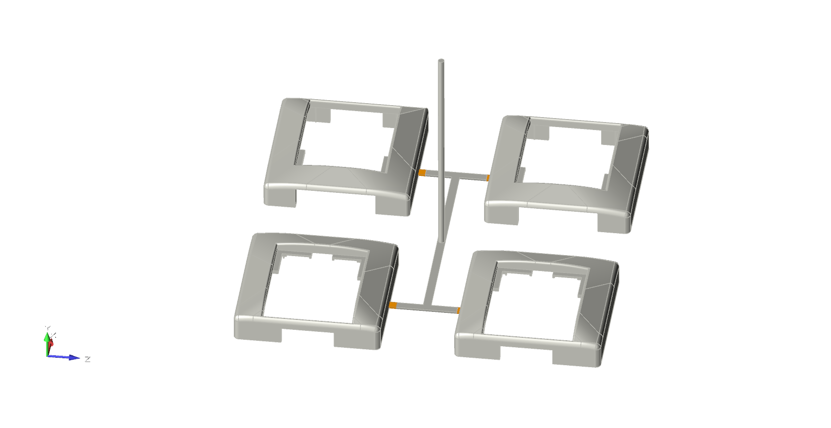
Gate
Use the Gate tool to define the joint between the runner and the part where the material enters the cavity.
Location:
In Quick mode, find this tool in the Gating secondary ribbon.
In Advanced mode, find this tool in the Runner System secondary ribbon.
Add/Edit Gate
If your model geometry doesn't include gates, you can create and edit virtual gates in Inspire Mold.
-
In the Quick ribbon, click the Gating icon.

OR In the Advanced ribbon, click the Runner System icon.
-
Click Add Gate on the Gates
icon.

-
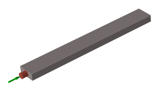
Click a surface on the part or runner to create a virtual gate.
Selected gates are displayed in dark red.
-
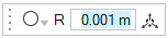
Use the microdialog options to define the gate's shape, dimensions, and
position.
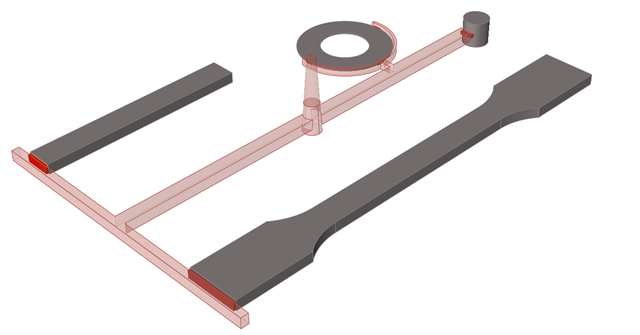
Designate Gate
Identify any gates that are included in your model geometry.
-
In the Quick ribbon, click the Gating icon.
OR In the Advanced ribbon, click the Runner System icon.
-
Click Designate Gate on the Gates
icon.

-
Select any predesigned gates.
Selected gates are displayed in dark red.
- Double right-click to confirm the designated gates.