Setting up Boundary Conditions
Set boundary conditions for Tool Deflection analysis, which requires loads and constraints.
Creating Pressure Loads
Use the Boundary Conditions tool to create the pressure loads.
Important: The default approach is not to create loads. Inspire Extrude will automatically create these for you.
Pressure loads are created only when you want to apply constant pressure load on the selected surfaces and nowhere else.
Inspire Extrude does not support load cases. All the loads in the model are used for analysis.
-
From the Tool Deflection ribbon, click the Boundary Conditions tool.

-
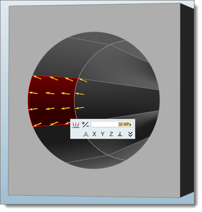
Click the surface on which the load is to be applied and enter the value of
pressure in the microdialog.
Loads created are displayed as arrows.
-
Edit the value by double clicking on the arrows.
Tip: The value of the applied loads can be seen in the Model Browser or by placing the mouse cursor on the loads.

Creating Constraints
Use the Boundary Conditions tool to create the pressure loads.
-
From the Tool Deflection ribbon, click the Boundary Conditions tool.

-
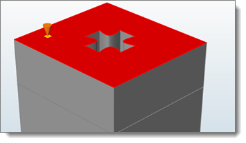
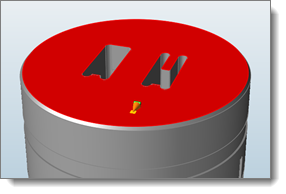
Click the surface on which constraints are to be applied.
The constraints are created.

- Verify if the constraints are created as required.
-
To change the constraints, double click on them. Inspire Extrude
allows constraints in any combination of X, Y, and Z.
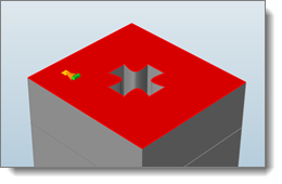
Three arrows showing 3D coordinate axis appears. Each arrow represents the coordinate in which the component is allowed to translate. For example, in the figure on the left, the green arrow represents that the model is allowed to move in Z direction and is constrained not to move in the X and Y direction. You can pick the direction to constrain/move based on model requirements. The figure on the right shows the depiction of applied constraint.

