
What Is Crack Analysis in Sintering?
Sintering is a high-temperature process that transforms loosely bound powder aggregates into near-net-shaped objects with controlled amounts of porosity. When a powder aggregate is sintered, its structure evolves to lower its excess surface energy. Necks grow between adjacent particles to reduce the local curvature at their contacts, and the entire aggregate densifies to eliminate the surface area.
In many sintering applications, external restraints can prevent a powder aggregate from densifying in one or more directions. Friction, for example, can prevent a thin film sintering on a rigid substrate from shrinking in the in-plane directions. Under these constrained sintering conditions, internal stresses can develop in the sintering material, and in extreme cases, these stresses can grow so large that they tear the aggregate apart. This fracture process, referred to as sinter-cracking, degrades product quality, lowers the yield, and proves highly undesirable.
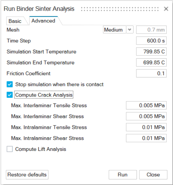
- Max Interlaminar Tensile Stress
- Max Interlaminar Shear Stress
- Max Intralaminar Tensile Stress
- Max Intralaminar Shear Stress
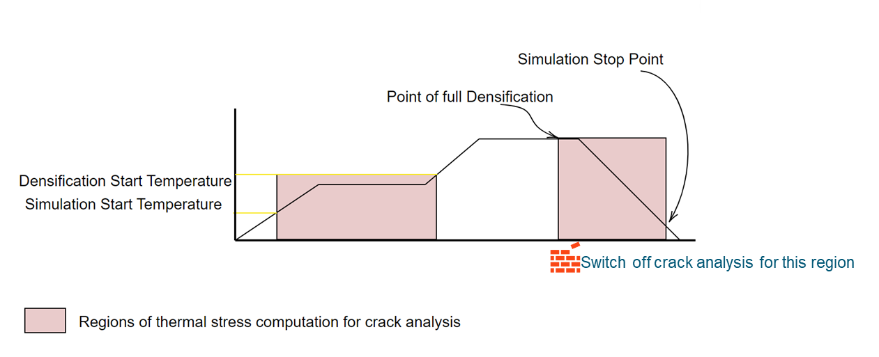
- No densification is assumed due to thermal expansion/contraction.
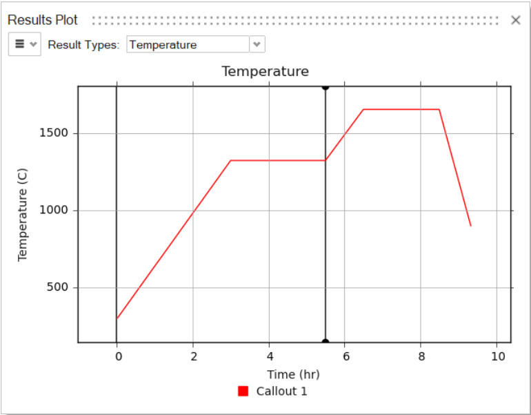
- The simulation start temperature is set as the part initial temperature.
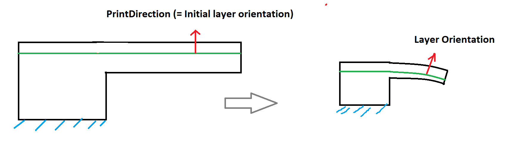
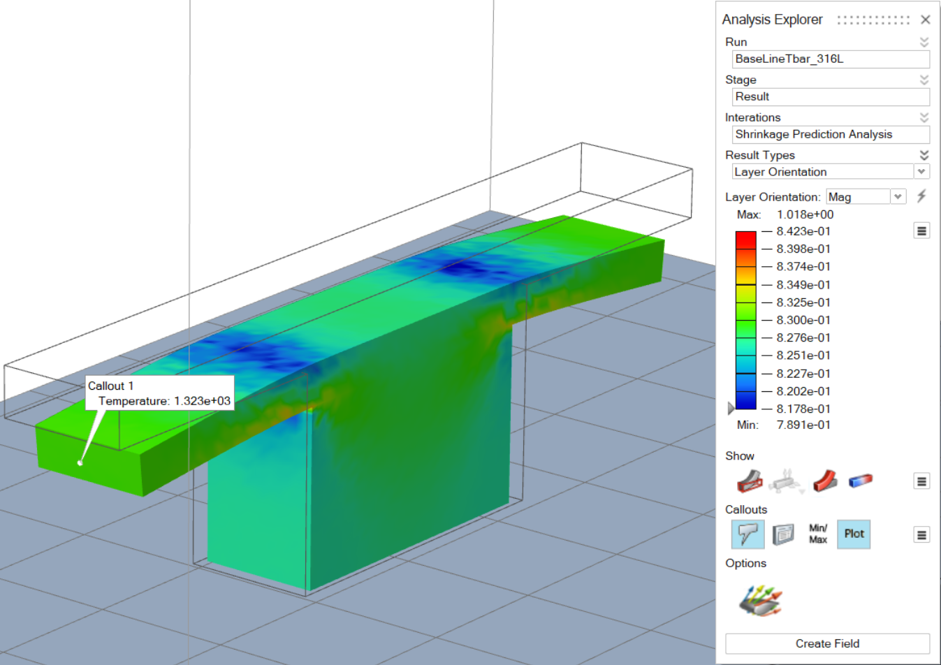
Layer Orientation:
The print direction is the initial layer orientation. Here "layer" refers to the layer of the powder, and the orientation refers to the normal of the layer.
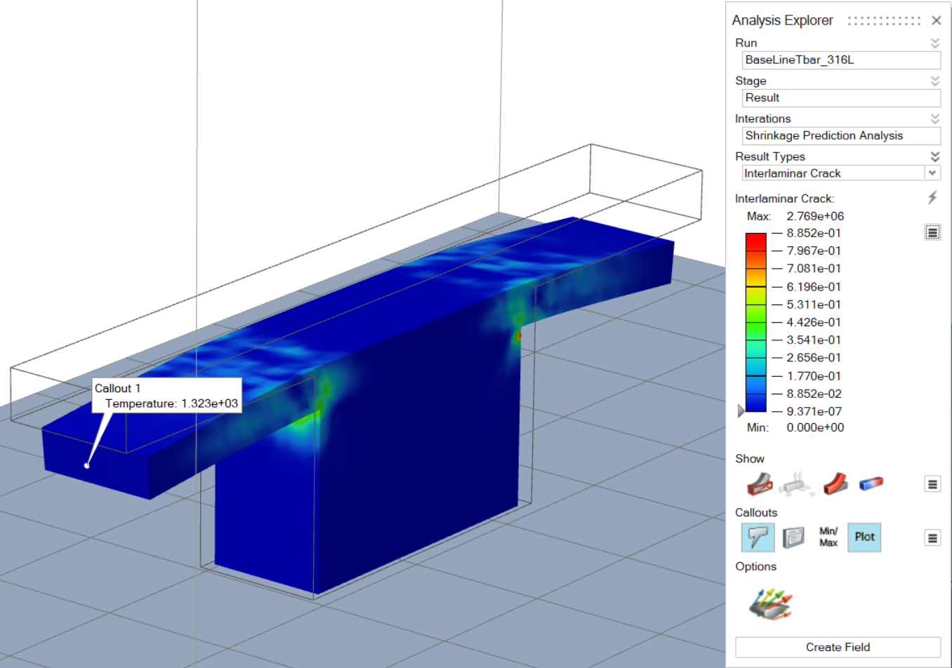
- The plot shows the evaluated value of the Hashin-type combination of inter-laminar failure.
- *Plot below is shown at a densification start temperature (End of region 1).
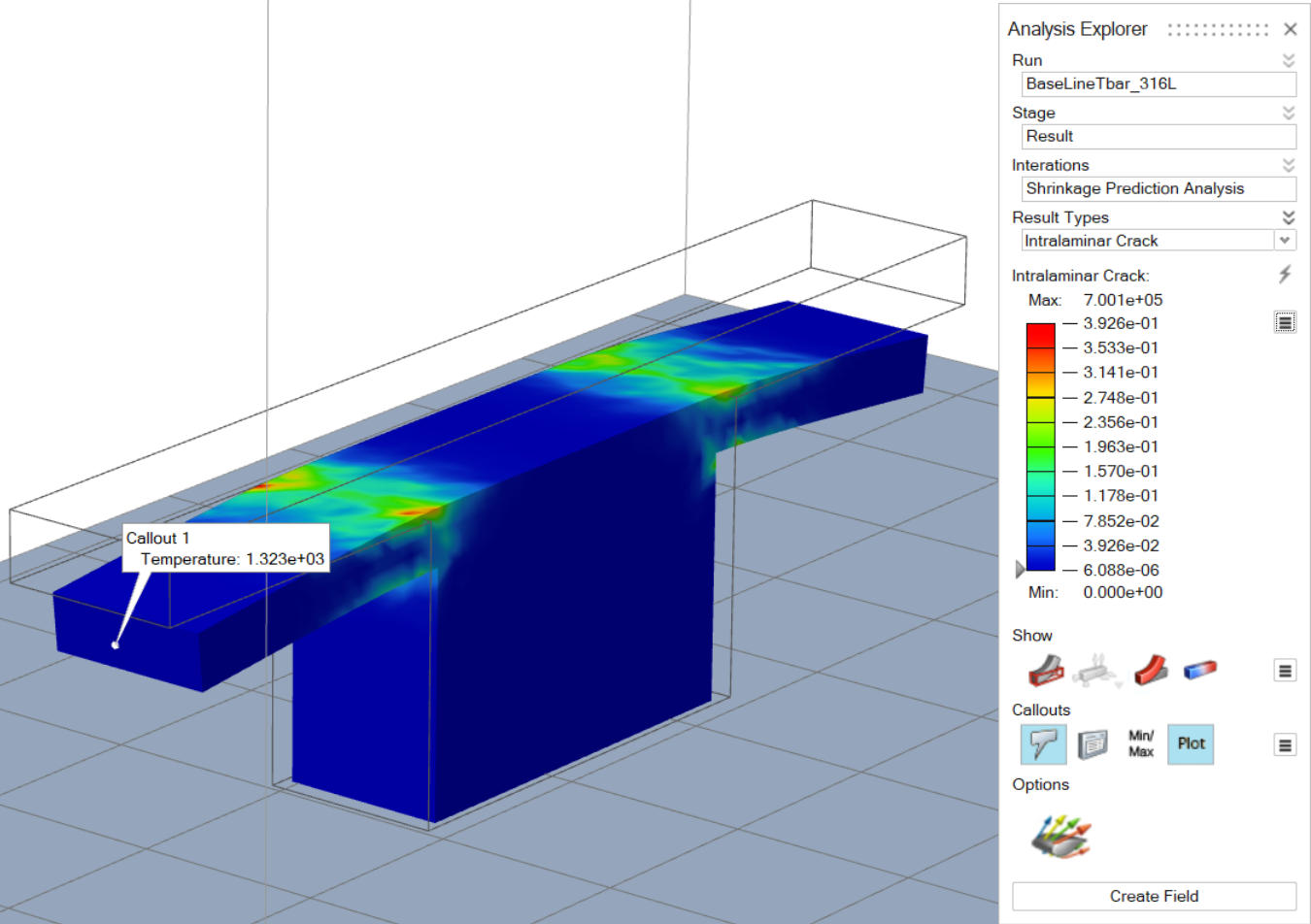
- The plot shows the evaluated value of the Hashin-type combination of intra-laminar failure.
- *Plot below is shown at a densification start temperature (End of region 1).
- We only predict failure due to tension and shear. We don't consider failure due to compression in sintering.
- The solver uses the standard procedure to evaluate the stress tensor using Hashin's criteria for interlaminar and intralaminar failure of laminates. This theory was originally developed for composites. Interlaminar occurs on the plane between the plies and in the case of sintering between two printed layers. Intralaminar occurs in a single layer.
- This evaluation involves computing the layer orientation, stress tensor, and traction vector using the layer orientation.
- The results of this analysis very much depend on the accuracy of the input data – the max intralaminar, interlaminar tensile & shear stresses. In theory, the cracks are likely to occur when the evaluated value is equal to or greater than 1.
- The computation of this criteria requires comparing the (square of) computed tensile/transverse and shear stress against the given input. If the input is wrong, so will be the failure evaluation.
- The predicted results are valid only during the debinding stage and until the end of this stage.