Spotweld (Bolt or Adhesive Connection)
- Nodal connection
- Spring (/PROP/TYPE13) connection
- Solid connection
Spring (/PROP/TYPE13) connection and solid connection may also be used to model a bolted or adhesive connection (glue).
Nodal Connection
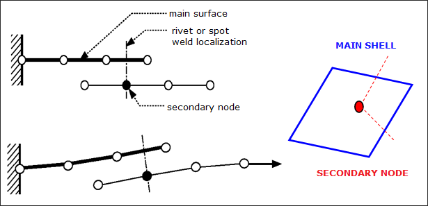
Figure 1. Example of Connection between 2 Shell Surfaces
Spring (/PROP/TYPE13) Connection
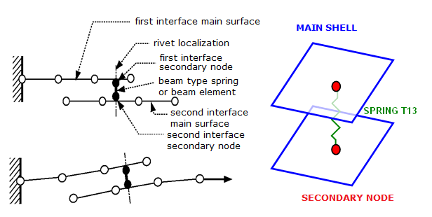
Figure 2. Spotweld Modeling
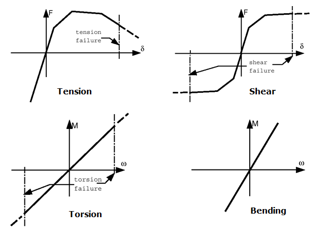
Figure 3. Spring TYPE13 - Typical Input for Spotweld
- Use failure criteria which are available for a spring TYPE13. For more details, see the comments for failure criteria in /PROP/TYPE13 (SPR_BEAM).
- Use Spotflag= 20, 21, or 22 in the Tied Contact (Tied Contact (/INTER/TYPE2)).Note: The spring TYPE13 modeling technique for spotwelds can also be used for other kinds of connections such as welding lines, hemming, glue and bolts. For bolt modeling, the use of a tied interface is not necessary, as the shell nodes can be put directly in the rigid bodies.
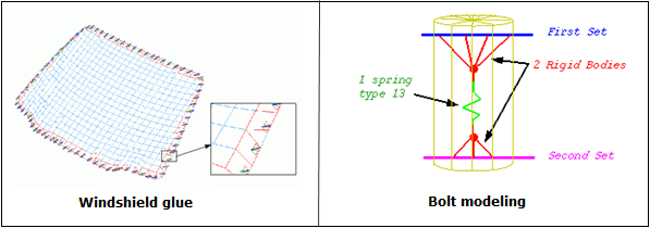
Figure 4. Glue and Bolt Modeling Examples
-
- Added mass
- Distance between the main node and the center
- Inertia of the secondary node
-
- Secondary node mass
- Distance between the secondary node and the center
- Inertia of the secondary node
If Spotflag=0, there is no added mass, since the secondary node inertia instead is transferred as inertia to the main node. An added inertia that is too large will seriously decrease the accuracy.
Solid Spotweld
Uses 8-node brick element (with /PROP/TYPE43) and /MAT/LAW59+/FAIL/CONNECT (or /MAT/LAW83+/FAIL/SNCONNECT) to model solid spotwelds, which may provide more accurate results.
Solid Element and Property
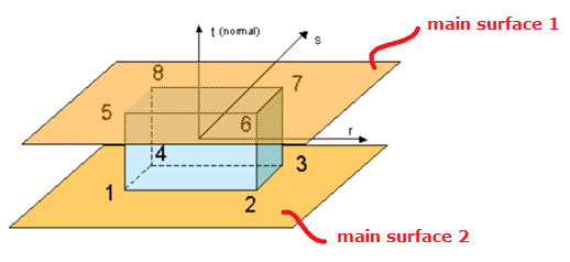
Figure 5.
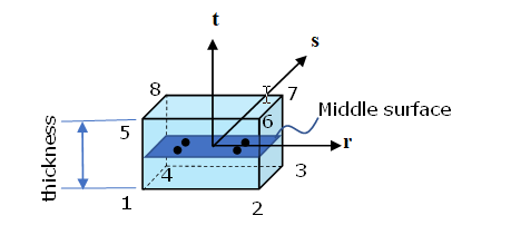
Figure 6.
Connected to Shell Sheet
/INTER/TYPE2 may be used to connect solid spotwelds with two (upper and lower) main surfaces. Nodes of plane (1,2,3,4) tied on one shell, and nodes of plane (5,6,7,8) tied on another shell. It is not allowed to have any other plane (for example, plane (1,4,8,5)) tied on a shell.
Material and Failure Model
- Shear test (angle of loading and spotweld upper surface is 0 degrees below named 0 degree test)
- Normal tensile test (90 degree test)
- Shear and normal combined test (for example, 30 degree test, 45 degree test or 90 degree test)
- Moment test (peel test)
E-Modulus
The stiffness of the spotweld in different tests is different. In the normal test, it is lower than in the shear test, due to deformation of the upper and lower sheets. Therefore, normally the stiffness measured is taken from true stress versus displacement curve of the shear test.
/MAT/LAW59+/FAIL/CONNECT
- Material yield
curve:In LAW59, spotweld material yield curves in normal direction and in shear direction are requested. The yield curve (Y_fct_IDN) in normal direction may be determined from the normal tensile test (90 degree test) and the yield curve (Y_fct_IDT) in shear direction may be determined from the shear test (0 degree test).
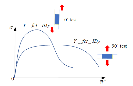
Figure 7.In this case, the maximum stress is also described inside the curves. Given the reference displacement rate of the input yield curve, Radioss will consider the displacement rate effect with respect to this reference displacement rate.
- Spotweld
failure:Solid spotweld damage and failure may be considered with /FAIL/CONNECT. Displacement criteria and/or energy criteria may be used to describe the failure of the spotweld.
- For
displacement criteria, failure occurs when the normal
displacement or shear displacement is reached according to 2
alternative behavior types:
- Uncoupled failure (Ifail=0: uni-directional failure)
(2) with = 33 for normal direction and = 13 or 23 for tangent directions.
In the normal tensile test (90 degree test), element fails once user-defined maximum displacement is reached.
In the shear tensile test (0 degree test), element fails once user-defined maximum displacement is reached.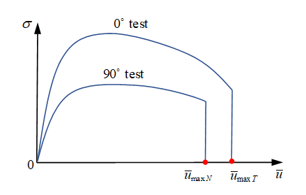
Figure 8.In a combined mode test (for example, 30 degree test or 60 degree test), failure in the solid spotweld does not consider shear and normal combined stress effect. Failure in each direction is considered separately. The element fails as soon as either of these two stresses reaches its corresponding maximum displacement. To consider combined stresses, instead set Ifail=1 and combined stress effect will be then considered.
- Coupled failure (Ifail=1: multi-directional failure)
(3) With Ifail=1, in combined mode test, the element fails before reaching the maximum stress or which is closer to reality. To describe the curve failure surface you need at least 4 different combined tests to fit the parameters .
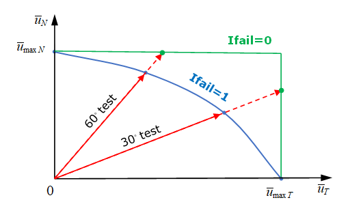
Figure 9. Failure surface
- Uncoupled failure (Ifail=0: uni-directional failure)
- For
energy criteria, failure occurs when the internal energy in
normal direction or internal energy in shear direction is
reached, corresponding to maximum internal energy .
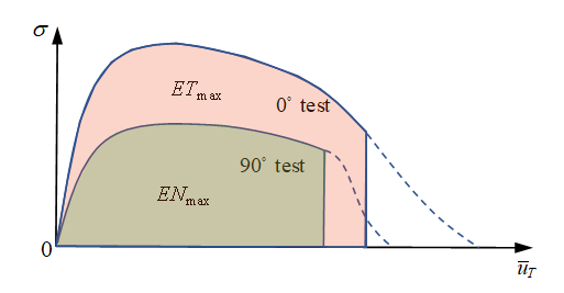
Figure 10.In a combined mode test, element failure is also considered with respect to the multi-direction effect on internal energy. If internal energy in normal direction and in shear direction are input, the element fails, if satisfied via:(4) To input only total internal energy , the element fails, if satisfied via:(5) If both and are input, the element fails, due to whichever of these two criteria is reached first.
Both displacement criteria and energy criteria may be defined. The element fails, due to whichever criteria is reached first. The element deletion occurs when one integration point reaches the failure criteria, if Isolid=1 or when all integration points reach the failure criteria, if Isolid=2.
- For
displacement criteria, failure occurs when the normal
displacement or shear displacement is reached according to 2
alternative behavior types:
- Spotweld
softening:After reaching the failure criteria (either displacement criteria or energy criteria) stress is reduced to 0 directly or may be gradually controlled with parameters and with:
(6) 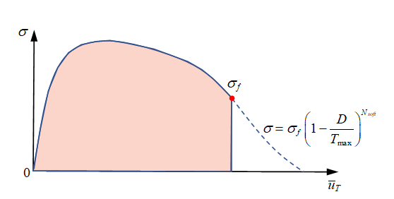
Figure 11.Figure 12 shows the effect of different and on stress reduction behavior.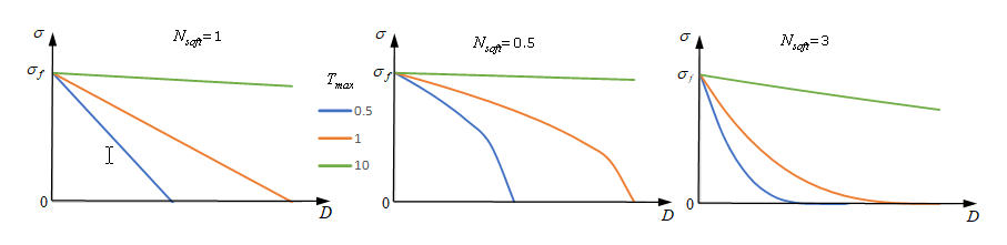
Figure 12.
/MAT/LAW83+/FAIL/SNCONNECT
- Material yield
curve:In LAW83, the spotweld material curve may be input with fct_ID1. Where in LAW59 input, two yield curves for normal direction and shear direction are required, LAW83 uses just one curve. This curve should take the yield curve from shear test. Furthermore, the yield curve fct_ID1 for LAW83 is not defined as true stress versus plastic displacement (as in LAW59), but should be a normalized stress versus plastic displacement curve. Yield stress is normalized by maximum stress which are input as parameters in LAW83.
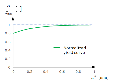
Figure 13.The yield curve is different due to different combinations of normal stress and shear stress in the spotweld. This may be described with parameter in LAW83 (it is not considered in LAW59). The normalized yield stress in LAW83 is:(7) In cases where the moment effect is not considered, the normalized yield stress in LAW83 is:(8) Figure 14 shows the difference of normalized maximum stress in combined tests between LAW83 and LAW59.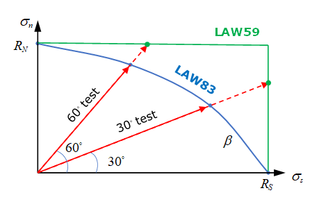
Figure 14.Figure 15 shows the effect of varying on normalized maximum stress in combined tests using LAW83.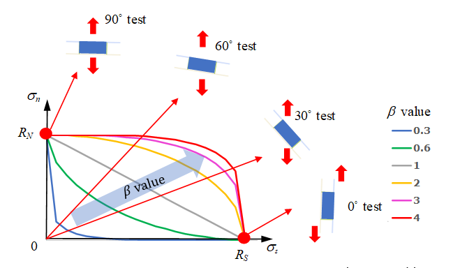
Figure 15.Parameter is used to describe the moment effect in the spotweld.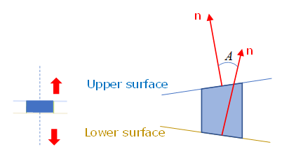
Figure 16. Non-central tensile test (peel test)Use to reduce the maximum stress of peel test. is the sin of the angle between the spotweld upper surface and lower surface. It is changed during spotweld deformation and is in range of [-1,1]. The parameter may be fitted with a simple FEM model to match the real experiment data. 1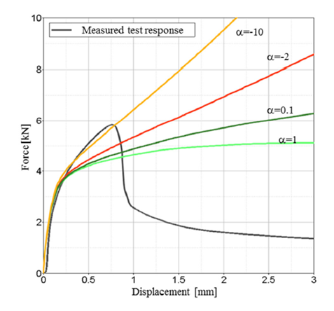
Figure 17. Different effects on peel test on force versus displacementThe displacement rate effect on the material yield curve may also be considered with curve inputs fct_IDN and fct_IDS.
- Material damage
and failure:For spotweld failure, /FAIL/SNCONNECT may be used. In this failure model, the plastic displacement (in both normal and shear directions) of damage beginning and failure are needed.
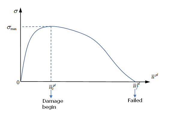
Figure 18.For a combined mode test, similar to maximum stress in LAW83, is needed to describe plastic displacement at damage beginning and to describe plastic displacement at failure.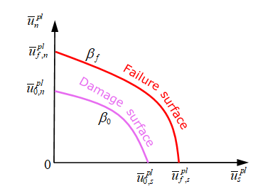
Figure 19.For spotwelds with moment (peel test), similar to maximum stress in LAW83, is needed to describe plastic displacement at damage beginning during the peel test and to describe plastic displacement at failure of peel test.Table 1. General Capability of the Two Spotweld Modeling Approaches /MAT/LAW59+/FAIL/CONNECT /MAT/LAW83+/FAIL/SNCONNECT Yield curve Two yield curves (in normal and shear directions) One normalized yield curve with maximum stress Maximum stress in combined mode test Normal and shear effect in combined test not considered. Use to consider normal and shear effect in combined mode tests. Failure Failure criteria Displacement criteria Uni-direction failure Multi-direction failure
Displacement criteria, Multi-direction failure
Energy criteria Uni-direction failure Multi-direction failure
Failure in combined mode test Proportionally controlled with in displacement criteria and with in energy criteria. Controlled with Moment effect (peel test)
No control in input Controlled with Softening With (stress curve decreases) With reference to damage displacement and failure displacement (stress linear decrease)