The Johnson-Cook failure model is often used to describe the ductile failure of
metals. It uses a Johnson-Cook equation to define failure strain as a function of stress
triaxiality.
In the Johnson-Cook failure model, there are three parts to the failure
model;
Where,
Plastic failure strain
Current strain rate divided by the input reference strain rate
Computed in the material law or /HEAT/MAT
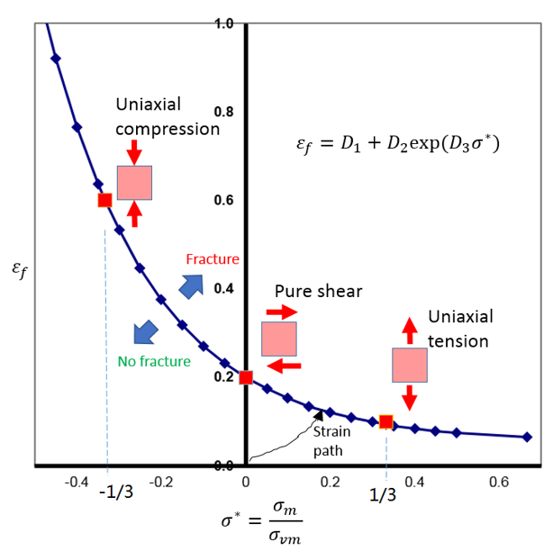
Ignoring the influence of strain rate and temperature a plot of the Johnson-Cook
failure is:Figure 1. Example Plot of a Johnson-Cook Failure Model
Plastic strains above the curve represent material fracture and below the curve no
material fracture.
In a simple case where only the triaxiality influence is considered, the failure
strain is:
Using 3 failure data points from test:
by uniaxial tension ()
by pure shear ()
by uniaxial compression ()
The parameters , and could be calculated analytically by solving the
following equations:
Element Failure treatment
A cumulative damage method is used to sum the amount of plastic strain that has
occurred in the element using:
What happens when depends on the values of element failure flags
(Ifail_sh
andIfail_so) and XFEM
formulation flag (Ixfem). When the
XFEM formulation is not used
(Ixfem=0), the following table
summarizes the different element failure flag options:
Table 1. Element Failure Options
Element
Element Failure Flag
If
Failure Behavior
Shell
Ifail_sh=1
(Default)
In 1 IP or layer
Element deleted
Shell
Ifail_sh=2
In 1 IP or layer
Stress tensor set to zero in IP or layer
Shell
Ifail_sh=2
All IP or layer
Element deleted
Solid
Ifail_sh=1
(Default)
In 1 IP
Element deleted
Solid
Ifail_sh=2
In 1 IP
Stress tensor set to zero in IP
Solid
Ifail_sh=2
All IP
Stress tensor set to zero in element
Details on the XFEM formulation
(Ixfem=1), can be found in
/FAIL/JOHNSON.
The damage, , can be plotted in animation files using
/ANIM/SHELL/DAMA or /ANIM/BRICK/DAMA. This
will show the risk of material damage.