Pattern grouping and shape variables can be used to optimize stamped plates that are
difficult to deal with due to corners and sharp edges.
Automatic generation of topography variables does not take into account situations in
which elements can be folded inside out when the variables are fully perturbed. This
limits the draw depth that can be used with that technique.
Model Files
Before you begin, copy the file(s) used in this example to
your working directory.
The following example demonstrates how this problem can be avoided with user-defined
variables. All optimization set up is done using the Optimization panel and its subpanels in HyperMesh.
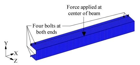
A hat section is centrally loaded, creating both bending and torsional loads (Figure 1). The hat section is constrained at either end by four bolts.Figure 1. Loads and Constraints for the Stamped Hat Section
It is preferable to have the size of the reinforcements able to run deeper than the
height of a single element. To ensure that this will not cause a problem with the
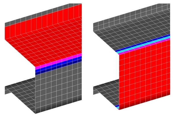
element mesh, three shape variables are created using HyperMesh and are added to the deck. The shape variables for
the face and top side of the hat are shown in Figure 2.Figure 2. User-defined Shape Variables for the Hat Section
Note: In Figure 2 the first three rows of elements adjacent to the elements being fully deflected
are a part of the user-defined shape variable for that side. Also, the draw depth is
equal to one and a half times the average element size.
It is desired to create this hat section using a stamping process which means that
reinforcing features on the sides of the hat must be constant (from top to bottom),
or else a die lock condition will occur. Pattern grouping can be used to create
variables that ensure manufacturability. For the three variables created for the hat
section optimization, planar pattern grouping was selected with the planes running
perpendicular to the length of the section (X-axis). The DTPG
card and associated DESVAR card for one of the variables
are.
(1)
(2)
(3)
(4)
(5)
(6)
(7)
(8)
(9)
(10)
DTPG
4
DVGRID
1
+
20.0
60.0
YES
+
PATRN
13
500.0
0.0
0.0
1.0
0.0
0.0
(1)
(2)
(3)
(4)
(5)
(6)
(7)
(8)
(9)
(10)
DESVAR
1
DV001
0.0
0.0
1.0
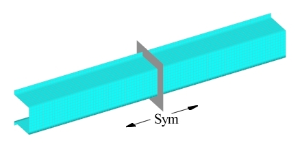
Additionally, a plane of symmetry was used to force both halves of the section to be
the same. Figure 3 shows the symmetry plane for the hat section.Figure 3. Plane of Symmetry for the Hat Section Model
Results
OptiStruct generates variables which allow for great
flexibility in the reinforcement possibilities, but which prevent a die lock
condition as shown in Figure 4.
Note: The area where the load is applied is left out of the face
variable.
Figure 4. Variables Generated for the Hat Section
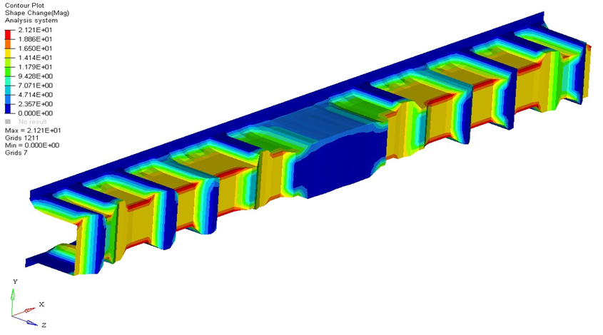
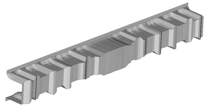
The objective is to minimize the compliance for the applied load. OptiStruct generated the shape shown in Figure 5.Figure 5. OptiStruct Solution for the Hat Section
Optimization
The solution generated by OptiStruct is manufacturable
using a stamping process. Also, the solution is very well behaved and needs little
refinement to turn it into a production-ready design.
The optimized hat section increases the stiffness of the part by more than eightfold
from the initial condition with no beads. The eight 'square' beads for the hat
section, especially the four at the ends of the beam, are the key to bolstering the
beam against shear collapse. Those beads also serve to prevent the flanges from
folding under the bending load. OptiStruct has generated
a strong design that supports both torsion and bending with restricted reinforcement
possibilities. The shape and placement of the reinforcements are optimized resulting
in a very efficient solution.