OS-V: 1010 Complex Eigenvalue Analysis of Rotor Bearing
System
Rotor Bearing system is an excellent example of rotating machines used in mechanical
engineering applications.
Analysis of this system to get unbalanced response, critical speed, resonance
frequency and vibration modes is important to evade the catastrophic failure of
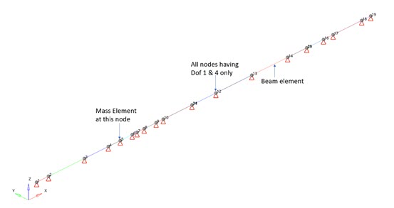
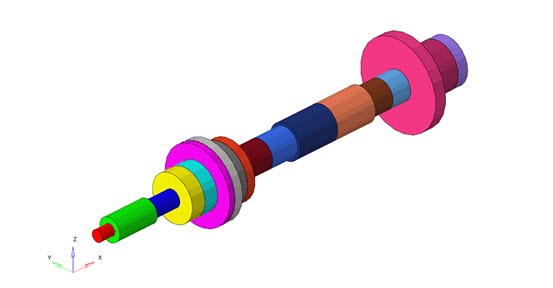
these systems. Here the critical speed of a Rotor Bearing system using OptiStruct is verified. 1Figure 1. 1D Rotor Model Figure 2. 3D Representation of Beams
Model Files
Before you begin, copy the file(s) used in this problem
to your working directory.
The finite element model, as shown in Figure 1 is constrained at all the nodes. Only DOF 1
and 4 are allowed on all the nodes. The model is meshed with beam elements of
different sections (Figure 2). Mass is attached at node 5. An isotropic
system is assumed.
Material
The material properties are:
Property
Value
Young's modulus
207.8 GN/m2
Density
7806 kg/m3
Bearing (undamped and linear) with following stiffness matrix are used in this
model.
k22 = k33
= 3.503 x e7 N/m
k23 = k32
= -8.756 N/m
Two different approaches are used in OptiStruct to input
the Bearing Stiffness in the model.
DMIG
The stiffness matrix of the bearing is defined directly in the model as
multiple column entries using K2GG.
GENEL
A file (.inc) which contains the details of bearing
stiffness is imported in the model.
The problem has been solved for Complex Eigenvalue Analysis (ASYNC).
Compare the whirl speeds at spin speed being 100,000 RPM.
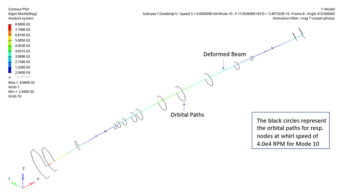
Results
The results are plotted over a range of spin speed for 12
different modes. The deformation of the Rotor Bearing system can be visualized in
HyperView by importing an .h3d
file.Figure 3. Eigen Mode Contour Plot for Spin Speed of 4.0e-4 RPM and 10th
Mode
Comparison of results at speed 100,000 RPM.
Table 1. Critical Speeds Comparison for Whirl Ratio 1
Here, you have verified that the whirl speeds obtained by OptiStruct for various modes are a close match with those
mentioned in the Nelson McVaugh Paper.
Nomenclature
Whirl Speed
The damped natural frequency of the rotor.
Backward Whirl (BW) and Forward Whirl (FW)
At zero shaft speed, the forward and backward frequencies are identical
(repeated eigenvalues). As speed increases, each vibration mode is split
into two modes, known as forward and backward precision modes, due to
gyroscopic effect.
1 Nelson,H.D. and McVaugh, J.M. (1976) The Dynamics of Rotor-Bearing
Systems Using Finite Elements. ASME Journal of Engineering for Industry,
98,593-600