MV-2040: Load Estimation for a Fore Canard Actuator Mechanism Under Aero-dynamic Loads
Tutorial Level: Advanced In this tutorial, you will learn how to represent pressure/distributed loads as Modal Forces on a CMS flexible body and scale Modal Forces to real world loads in MotionView/MotionSolve.
Forces acting on a flexible body may be an aerodynamic load, liquid pressure, a thermal load, an electromagnetic force or any force generating mechanism that is spread out over the flexible body, such as non-uniform damping or visco-elasticity. It may be even a contact force between two bodies. These distributed loads can be conveniently transformed from Nodal to Modal domain and represent as Modal Forces.
If we define  as the mode shapes of the flexible body, and
  as the Nodal load acting on the flexible body, the
equivalent Modal load on the flexible body
  is defined as:

Create a Fore Canard Flexible Body
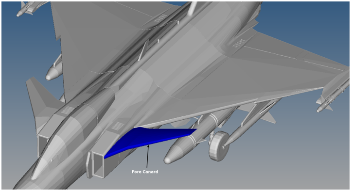
In this step, you will create the Fore Canard flexible body.
- Open ForeCanard.hm in HyperMesh with OptiStruct selected as the user profile.
-
Review the model.
Figure 2. 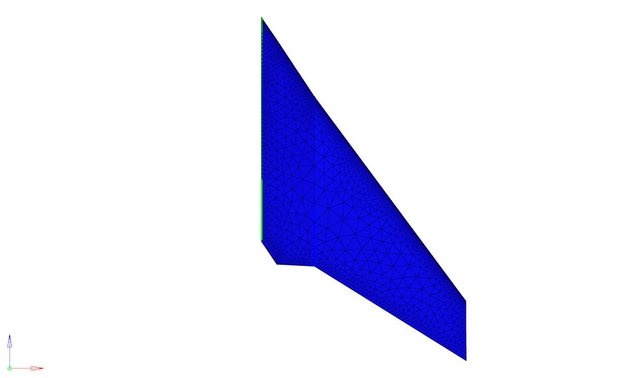
-
Create aerodynamic loads from CSV files.
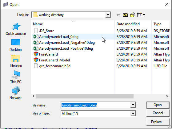
Average pressure distribution over the surface of canard is exported as text file from AcuFieldView. This file contains the location and value of the pressure. The AerodynamicLoad_0deg.csv, AerodynamicLoad_Negative10deg.csv, and AerodynamicLoad_Positive10deg.csv files contain the pressure distribution information for 0deg, -10 deg, and 10 deg of canard orientation respectively.Add load collectors for three cases:
-
Browse to the Pressure load panel.
-
Set the pressure load type to linear
interpolation.
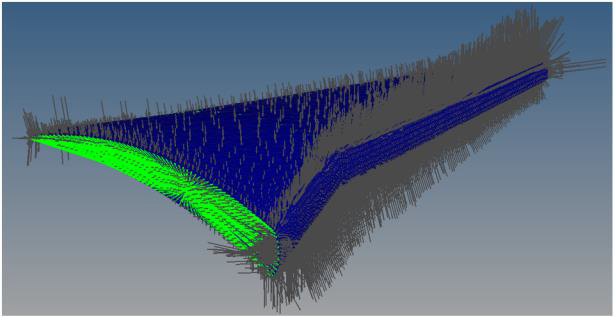
Now you can select elements on which pressure loads are applied and a CSV file for pressure load info.
Figure 11. 
-
Create pressure loads on a canard surface.
Pressure loads for each position are created under their respective load collectors so you can scale them in MotionSolve with respect to the canard position.
-
Specify load sets for CMS method.
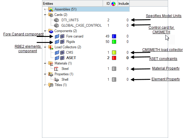
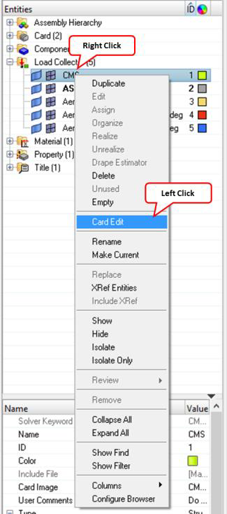
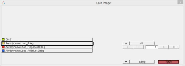
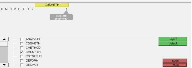
Three load cases modeled in previous step represent nodal forces. These nodal forces are transformed as modal forces using CMS method. In this step you modify the existing CMSMETH card image to include three load sets.
-
Specify load sets for CMSMETH.
-
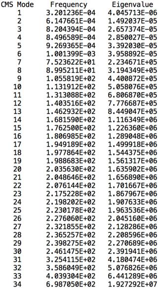
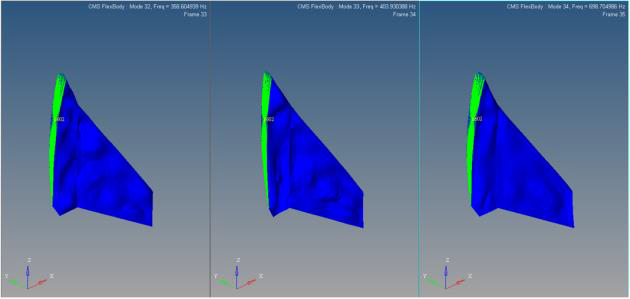
Generate flexbody.
Your model is now ready for solving to generate a flexbody. The two control cards required to solve for flexbody creation are already specified in the model.
Create a MotionView Model
In this step, you will create a MotionView model of the Fore Canard.
-
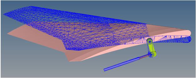
Open the ForeCanard_Model.mdl in MotionView. Review the model.
The model contains the following elements:
- Four bodies namely Fore Canard, Torque Arm, Piston, and Cylinder.
- A motion on the Piston with an expression 0.025*SIN(2*PI*TIME) to extend
and retract the piston by 25mm at 1 Hz. This piston motion varies the
fore canard angular position between -9.619 deg to +9.984 deg.
Figure 35. 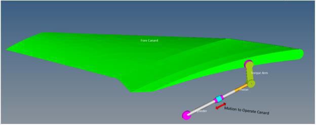
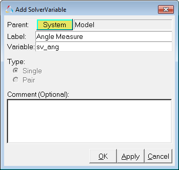
- An expression type Output request to measure the “ForeCanard angular
position” and “Piston force along its axis”. The Fore canard angular
position is measured from the
RevJnt_TorqueArm_Gnd joint rotation
angle using the expression
`RTOD({j_4.AZ})`. The Piston force is
measured from the Piston Motion using the expression
`MOTION({mot_0.idstring},{0},{4},{j_2.i.idstring})`.
Figure 36. 
-
Solve the model with the rigid Canard to review piston forces without
aerodynamic loads.
- Return to MotionView.
-
Switch the rigid fore canard to a flexible body.
-
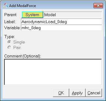
Model Aero-dynamic loads through Modal Force Entity.
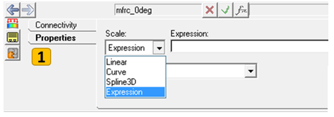
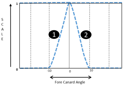
The aero-dynamic loads are estimated at three distinct positions of canard namely - 10 deg, 0deg, 10deg. Assume each pressure load to linearly vary in interval ±10deg on a 0 to 1 scale. This variation of the aero-dynamic loads is achieved by scaling Modal Forces with respect to canard angle using an expression.
-
Configure the ModalForce panel.
Solve and Post-Process the Model
In this step you will run the Fore Canard model with the flex body and post-process the results of the run.
-
Click the
 (Run) panel icon.
- Specify the MotionSolve file name as ForeCanard_withAeroloads.xml.
- Specify the Simulation type as Quasi-static, the End time as 1 second, and the Print interval as 0.01.
- Click Run.
-
After the simulation is complete, click the Animate
button to view the animation in HyperView.
You can use the
 (Start/Pause Animation) button
to play the animation.
 -
Click on the
 (Contour) panel button.
- In Contour panel under Result type, select Stress (t) and click Apply.
-
This will show you the stress contours.
Figure 51. 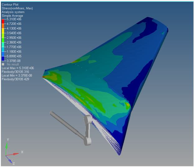
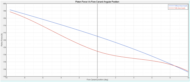
- In the MotionView run panel, click Plot to load the ForeCanard_withAeroloads.abf file in HyperGraph 2D.
-
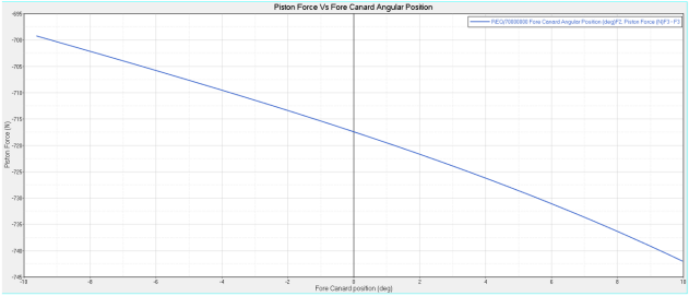
Plot the Piston Force versus the Fore Canard Angular Position by selecting the
information specified in Table 4 and Table 5.
Table 4. X-axis Data X Type Expression X Request REQ/70000000 Fore Canard Angular Position (deg)F2, Piston Force (N)F3 X Component F2 Table 5. Y-axis data Y Type Expression Y Request REQ/70000000 Fore Canard Angular Position (deg)F2, Piston Force (N)F3 Y Component F3 Figure 52. 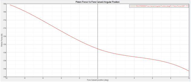
Note: You can overlay the plots to observe the difference in piston forces with and without aero-dynamic forces.Figure 53. 