Exercise 3: Run Your Simulation with Usersubs
In this exercise, you will run the simulation with the usersubs you implemented in Exercise 2: Add User Subroutines and compare the results to those from your initial test in the Exercise 1 step Run the Model.
Run the Model
In this step you will run the model with implemented usersubs.
-
On the toolbar, click
 (Run).
- In the Run panel, click the Run MotionSolve file radio button.
-
Use the
 (Open) button to browse to the
*.xml file save in the step Use DMPSUB to Add Custom Flexbody Damping.
(Open) button to browse to the
*.xml file save in the step Use DMPSUB to Add Custom Flexbody Damping.
Figure 1. 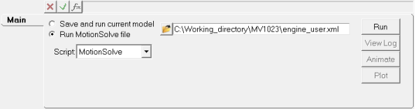
- Click the Run button.
Use HyperGraph to Plot the Displacement Magnitudes
In this step you will use HyperGraph and the outputs from both simulations to compare the displacement magnitude of the piston.
-
Click the
 (Add Page) button.
-
From the Client Selector drop-down menu, switch the client from MotionView to HyperGraph 2D.
Figure 2. 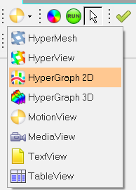
-
Plot the baseline results.
-
In HyperGraph, click the
 (Build Plots)
icon.
(Build Plots)
icon.
-
In the panel, use the
 (Data File browser) to open the
baseline_abf file.
(Data File browser) to open the
baseline_abf file.
- Leave the default x variable (Time). For Y Type, select Marker Displacement. For Y Request, leave the default. For Y Component, select DM.
- Click Apply.
-
In HyperGraph, click the
-
To plot the usersub results, repeat step 3. For Y Type use
REQSUB and for Y Component use RESULT
(2).
Figure 3. Comparison of output results from both model simulations 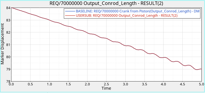
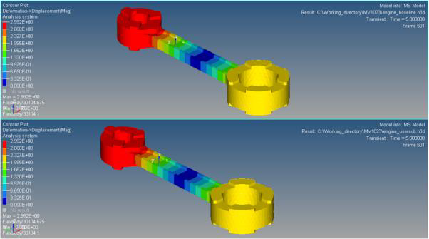
Use HyperView to Compare Flexbody Stresses
In this step you will use HyperView to compare the stresses and deformations on the flexbody.
-
Click the (Add Page) button.
- In the Client Selector drop-down menu, switch the client from HyperGraph 2D to HyperView.
-
On the Standard toolbar, click the
 (Load Results) icon.
- From your <working directory>, open the baseline_h3d results file.
- Click Apply.
-
Click the
 (Entity Attributes)
button.
(Entity Attributes)
button.
-
In the panel, next to the Display option, click the Off
button.
Note: Make sure that the Auto apply mode check box is checked.
Figure 4. 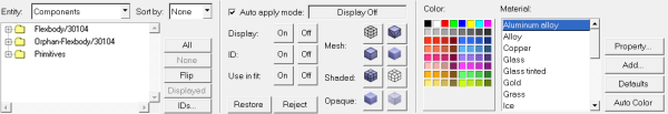
-
In the modeling window, click on the piston head, and
both crank components.
Note: Only the flexbody component should be displayed.
-
On the Results toolbar, click the
 (Contour) button.
-
In the Contour panel, set the Result type to
Deformation->Displacement (v) and click on the
flexbody in the modeling window.
Figure 5. 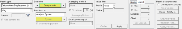
- Click Apply.
-
Next, click the
 (Tracking Systems) icon.
- In the Tracking panel, from the Track drop-down menu click Component. Then click the flexbody in the modeling window.
-
On the Page Controls toolbar, open the Page Window
Layout drop-down menu and click
 (two window layout).
- In the blank modeling window, repeat steps 3 through 13 for the usersub h3d file.
-
On the Animation toolbar, click the
 (Start/Pause Animation) button to animate your
models.
(Start/Pause Animation) button to animate your
models.
Figure 6. Comparison of flexbody deformation in HyperView