Model class methods (Modify and Query functions) are fully documented in the
Python API documentation.
CollectionByInteractiveSelection() now accepts a collection object as input
allowing you to modify an existing collection, as well as create a new
collection object.
Model class method get() signature has been updated to accept an entity
class and query string, providing a faster way of retrieving a single
entity.
Class representing the Assembly entity type has been added to the
hm.entities module.
New Model class methods have been added to provide information about
HyperMesh model: hm_info(), hm_info_currentcollector(), hm_info_emptylist(),
hm_info_unusedlist().
New classes, functions, and features have been added to the hwx.gui GUI
toolkit (for example, Canvas, OpenFileEntry, Toolbar, WebView, and so on).
A new output option has been added to Python Recording allowing the push of
recorded code to a Compose debugger session.
The Output Settings dialog in Python Recording provides options to restore
the defaults.
Enhancements
Performance of creating collections using FilterByAttribute() has been
improved.
A new element entity can be created using the Element class
constructor.
Collection class provides custom __str__ method and upon printing a
collection object, the information about entity class and size of the
collection is returned.
Python Recording adds an increment suffix to all variable names in order to
avoid clash with built-in Python functions.
Python Recording captures the assignment of parameters to entity attributes,
recording the corresponding parametrize_byentity() and
parametrize_bycollection() functions.
Python Recording GUI shows the argument value for all arguments that share
the same value definition. Previously, the value was shown only for the
first instance.
Resolved Issues
Multiple Model class methods have been updated to correct their argument
naming and typing. These changes can affect existing scripts and potentially
require script updates. See the Python API documentation for detailed
information on the individual methods.
Creating a Model class instance before initializing HyperMesh client would
lead to the application exiting unexpectedly. This has been mitigated by
introducing additional checks which trigger an error if hm package is being
imported in a session where HyperMesh client has not been initiated.
Access to multiple entity attributes has been resolved.
Known Issues
The following known issue will be addressed in a future release as we continuously
improve the performance of the software:
In the code recorded inside command.tcl, the line
continuation character ( \ ) might be incorrectly placed when splitting the
list of IDs referenced in a *createmark call into
multiple lines, resulting in breaking the ID range definition. You will need
to manually update the syntax to avoid an incorrect ID reference when
evaluating the recorded
code.
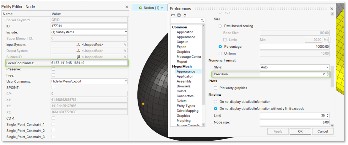
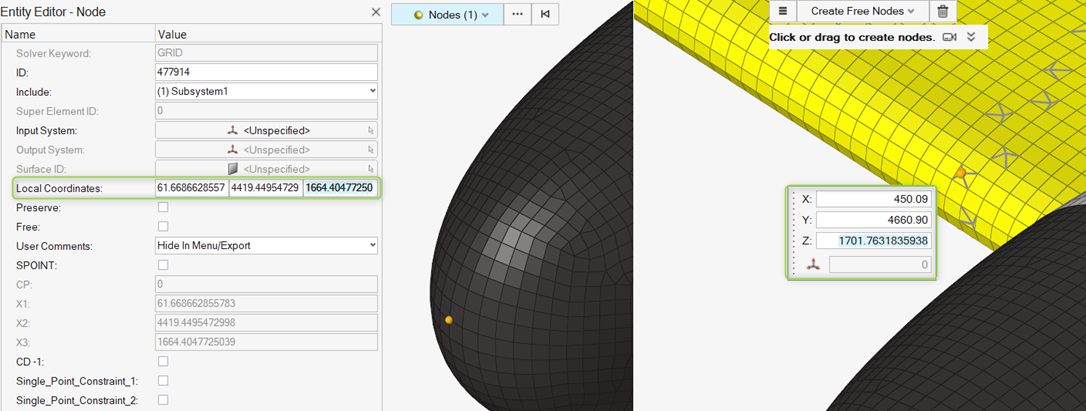
The Precision value preference for decimal display is now applied to the
coordinate editor in the Entity Editor as well as to all micro
dialogs.Figure 1.
Inactive editor: Decimal values are shown according to the precision
setting defined in Preferences.Figure 2.
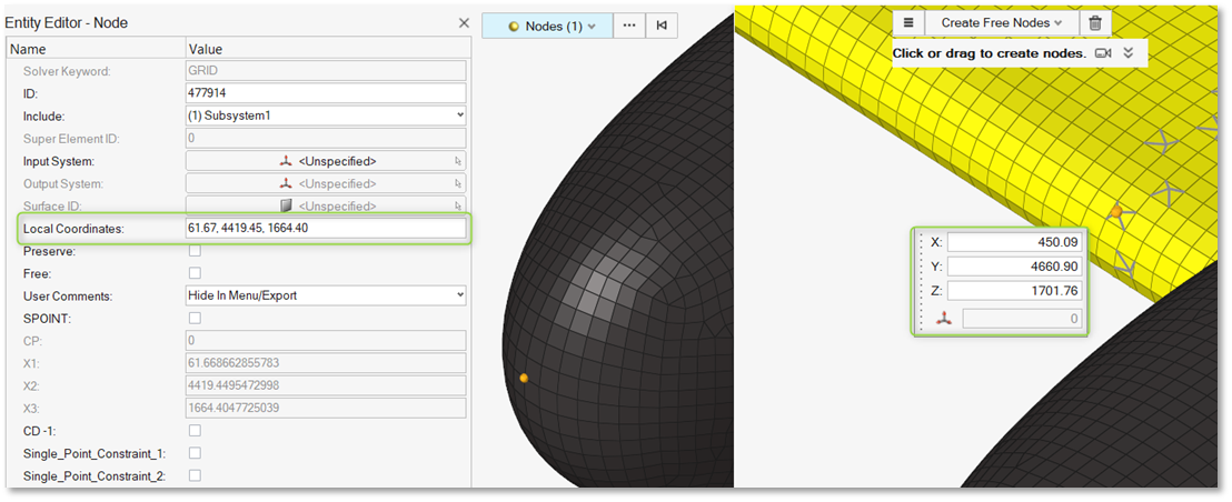
Active editor: Decimal values are displayed with up to 15 digits of
precision.Figure 3.
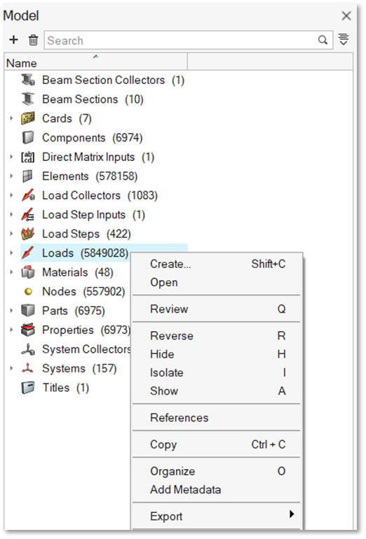
Enhanced Performance
In the Model Browser, accessing the context menu on the Loads folder is
now over 70% faster, even with extremely large models containing up to 5
million entities.Figure 4.
Resolved Issues
Decimal values were previously truncated in the Entity Editor's Coordinates
editor and all micro dialogs.
Selecting Include References caused a segmentation
error.
The Set type was not displayed correctly in the Type column of the Set
Browser.
Node references to local coordinate systems were not updated correctly in the
Reference Browser when references were set for additional nodes.
Changing the response type for optimization responses incorrectly moved entities
to the Ungrouped category.
Selecting all loads while in review mode caused performance issues.
Deleting assemblies from the Model Browser triggered an application error.
Updating the Thickness attribute for properties via attribute columns caused
performance degradation.
The Entity Editor became inaccessible after using Element Organization to New
Component.
The Auto Color feature was recoloring unselected components due to uncleared
marks.
Composites
New Features
Post-Processing
For the Abaqus solver interface, mapping section point results to actual
plies and their corresponding recovery planes allows much more effective
post-processing of results with layers. For details, see the Post release notes.
Enhancements
Composite Stress Toolbox
Composite Analysis Result viewer selection behavior for material and ply
engineering constants calculation is now in line with the behavior of
other analyses.
Resolved Issues
Composite Stress Toolbox
When deactivating plies/composites in the Entity State Browser,
the deactivated plies are no longer used in composite stress
toolbox calculations.
Previously, in rare cases with no failure criteria selected in
the first ply failure method for load response failure
calculations, a failure index was reported regardless. This is
now prevented by a different initialization routine.
Known Issues
Composite Stress Toolbox
MATF PUCK3D, TSAI3D, and HASH3 failure criteria only support
reading the allowables, but not the additional parameters (W1,
W2, W3). Standard set for those parameters for glass fiber and
carbon fiber is used as per ESAComp documentation for PUCK. F12
is used for TSAI3D. W1=alpha=1 is used for HASH3D.
Pre-Processing
Performance of laminate realization and graphics shift selection
of plies for large models.
FE Absorb Plies produces an incorrect result if input zone
properties do not have global names/IDs and there are ply drops
on top and bottom layers across properties to be absorbed.
Comprehensive support of LS-DYNA material orientation review is
not available.
Connectors
New Features
Attachments
Attachments with RBE3 or RBE3 (stuck node) support weight factor
calculation methods (inverse distance, normal distribution, constant
value) with the normalization option applied are now available. In the
Abaqus solver interface, these new options are available and applied on
the constraint entities that are being created.
Point Connectors
The new Weld (Imprint) realization has been added. It is a new type of
point connector, and it is supported in the LS-DYNA solver interface.
This new realization creates constraints and has imprint
capabilities.Figure 5.
Connector types that realize RBE3s now support a new option to set the
weight factors equal to a constant value based on your input.
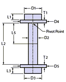
Fastener Connectors
Solid type fasteners now support the following:
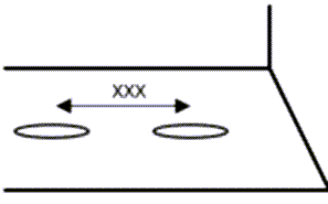
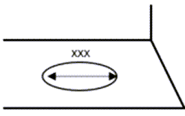
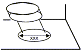
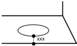
The new Pattern 6, which creates a bolt with double-sided head
and washers. A preview schematic with all the dimensions is also
available.Figure 6.
The Nastran solver interface. Contacts and pretension
definitions are added to match Nastran’s requirements.
Automatic calculation of a bolt’s shaft length and
diameter.
New options for refined mesh areas for evaluation near the
bolt’s head and shaft length offset based on shell
thickness.
Hole type fasteners now support body extensions. Two new options have
been introduced to account for the length of the bolt’s head and nut or
thread.
The Auto Fastener tool now supports the new "Only two layers" option.
This option limits the links to two. The "Only two layers" option
facilitates the automatic workflow as it eliminates the need for
tolerance fine tuning in cases where only two links are desired.
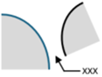
Clip type fasteners now support new patterns. You can use these options
to choose the type of clip you would like to realize the connector on,
based on its configuration. Previews of the each pattern are also
available.Figure 7. Figure 8. Figure 9.
Line Connectors
Line connector types that realize contacts now support the creation of
heat affected zones (HAZ). In particular, Contact, Hexa (Contact), and
Beam (Contact) now offer a new HΑΖ option in the controls. For Hexa
(Contact) and Beam (Contact), the HAZ option is only available when
local contact is selected.
Area Connectors
The new "Auto-trim" option in area controls has been added. When it is
enabled, all the areas that fail to find a projection are trimmed from
the connector when realizing.
Rigidlnk (midnode): a new type has been introduced for the Radioss
solver interface. This type will realize RBODY elements with their
independent node located in the middle.
Miscellaneous
A locking capability has been introduced for connectors. With the
locking capability, connectors can be realized and locked to prevent
them from unrealizing. Already realized connectors can be locked and
unlocked on demand. A locked connector is indicated in the Connector
Browser with the icon.
The RBE3 tool now supports weight factor calculation methods. These
include the inverse distance and normal distribution with normalization
options. An option to set the weight factors as a constant value has
also been introduced. These options are located in the tool’s guide bar
options menu.
A new option to organize the RBE3s manually has been introduced for the
RBE3 tool. Using this option, you can use the guide bar to choose the
component or part (only for the Abaqus solver interface) and where the
created RBE3s are going to be stored.
Enhancements
Attachments
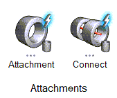
The Auto Attachments and Auto Connect tools have been introduced as
satellite options on the Connectors ribbon. These tools can be used to
create attachments based on hole recognition and connect them
automatically.Figure 10.
Creating attachments without an assigned control is no longer bound to
holes. Attachments can now be created on arbitrary locations. This
improves performance and facilitates attachment creation.
Point Connectors
Spring (rigid) type fasteners have been enhanced so that the realized
RBE3 elements attach to all nodes of second order elements instead of
only corner nodes.
Fastener Connectors
The Colinearity option has been relocated from the Preferences options
to the Hole type control. This way it can work locally on the connector
level instead of globally.
Line Connectors
Seam Quad:
Previously, connectors with the "Use Extension" option enabled
would create a poorly structured mesh. The process has been
improved and the resulting mesh is well structured.
Snapping options have been added to the control. As a result,
fine tuning the realization near free edges has been
improved.
Automatic weld recognition has been enhanced to identify cases
with mixed T and L welds.
The control has additional LTH and LTV options for weld size
dependent realizations. In particular, the "t1/2+wh" and "wh"
options have been introduced for LTH and the "wv" option has
been introduced for LTV.
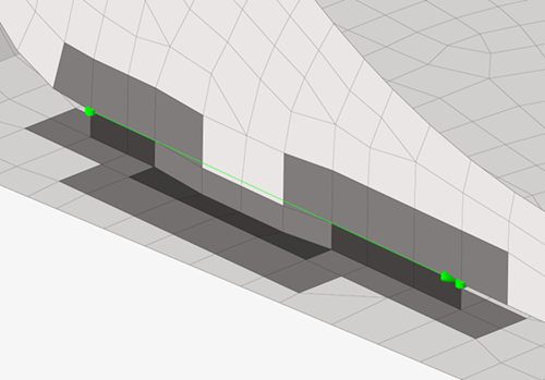
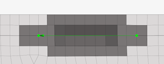
Realizations have been improved to be able to realize tabs and
slots use cases. This additional logic also supports imprinting
and HAZ creation.Figure 11. Figure 12.
Miscellaneous
The connector state icons have been redesigned to enable more intuitive
workflows and improved accessibility.
Figure 13. Realized
Figure 14. Unrealized
Figure 15. Failed
Figure 16. Modified
The default XML format when saving a connector representation has been
updated from XML2.0 to xMCF.
The "Consider only selected or displayed for absorb" connector
preference option has been added. This option is enabled by default.
When the option is enabled, only the elements manually selected and/or
displayed will be considered for connector absorption. In the case of
missing elements, either from the realization or the links, the
absorption will fail. This option results in better performance, but
requires a correct setup. When the option is disabled, the entire model
will be scanned; thus, greater flexibility is achieved at the cost of
performance.
Resolved Issues
The Seam Quad control has been fixed so it does not show any HAZ related
options when the Connectivity option is set to imprint/no
HAZ.
Seam Quad line connectors that were shaped as closed loops are now fixed and
the realization issues have been addressed for this use case so that the
realization is successful.
Shape type attachments have been fixed so their interface node ID respects
the Include’s ID range when they are realized, if applicable.
The "Ensure Projection" option for point, line, and area connectors has been
fixed to equivalence coincident nodes.
The "Update" option now applies only to realized connectors or realized
connectors with post errors.
Hexa (Contact) area connectors in the Radioss solver interface have been
fixed to use PENTA6DG elements. Property-element incompatibilities have been
fixed.
An outdated connector XML text block is no longer written in the solver deck
file during export.
Issues with exporting connector files using xMCF format have been fixed.
Export now should work as expected for all solver interfaces.
During solver deck export, redundant warning messages are consolidated into
one for cases when files contain connectors with incorrect pitch-to-length
values.
Unsuccessful realizations of fasteners that link attachments resulted from
applying scenarios are now resolved. Now, when using the apply all option
from the Scenario Manager, attachments will be first in
the queue followed by connectors.
Design Explorer
New Features
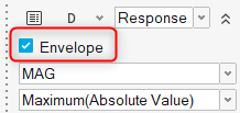
Envelope Response
A new envelope response is now available for displacement responses.
When selected in the microdialog during the response creation, the
envelope response will report the maximum displacement value for each
selected node across the entire exploration.Figure 17. A new Envelope Response tab in Results Explorer will report the
response values, and a corresponding envelope contour can be
displayed.
Compliance Response
A new compliance response is now available for explorations using
OptiStruct as a solver and can be created via the Mass/Volume Response
tool.
ExpertAI
ExpertAI, previously only available within Results Explorer, is now also
available as a standalone tool and can be used to reference both Design
Explorer and external explorations. Now it’s possible to open and use
DOEs and optimizations which may have originated outside of Design
Explorer.
Enhancements
Generative Design
The Generative Design workflow can now support multiple design spaces
simultaneously. Previously, you were forced to select a single design
space for concept generation.
The draw direction and symmetry design variables have been updated to
allow quick creation of primary planes in both positive and negative
directions. Previously, only positive directions were supported. Others
needed to be manually created.
Replicate Design Variables
Multiple replicate design variables can now be created at the same time
by selecting multiple lines. Previously, only a single line could be
selected, so replicate design variables had to be created one at a
time.
Replicate design variables can be created by selecting nodes. In this
special case, instance numbers will be automatically selected as 0 and 1
and cannot be changed.
For doublers and bulkheads, attributes of instances can now also be made
variable. Previously, only the number of instances was variable and all
properties were fixed.
Connector Design Variables
The Weld Length and Break Length attributes, which are available when a
connector’s Skip Welding attribute is selected, can now be considered
when creating connector design variables.
Miscellaneous Enhancements
Nominal runs are now optional. You how have the ability to select
whether or not to include a nominal run in your exploration.
You are now prompted when opening a model containing explorations if the
study path does not match the folder containing the opened model, and
the path is automatically reconciled if desired.
Exploration evaluation now occurs in a separate thread, so you can close
your HyperMesh session during evaluation if desired.
More interactive feedback is provided for failed exploration runs. By
moving the mouse over a failed exploration run, error information will
be displayed.
Other miscellaneous performance improvements have been done.
Design Space
Enhancements
Exoskeleton
Improved the mesh quality/aesthetics and removed duplicate 1D’s.
General
New Features
Selection
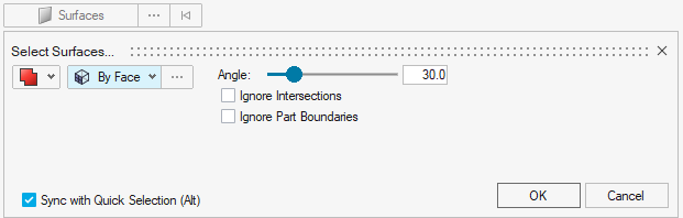
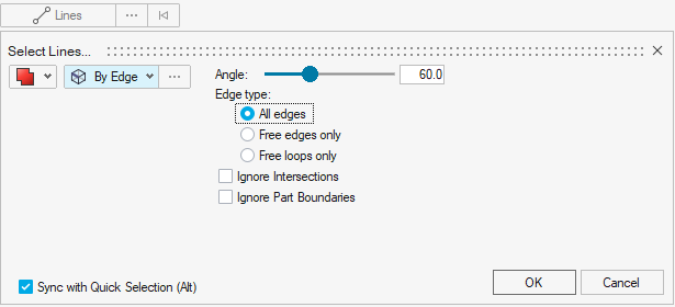
Feature angle based selection is now supported for surfaces and lines in
the user interface. The following new selection methods are available in
the Advanced Selection dialog and the “Alt”
selection switcher:
Surface > By Face
Surface > By Edge
SurfaceBy
Limit
Line > By Edge
Figure 18. Figure 19.
Enhancements
Selection
The All selector defaults to “Parts” if the
object is organized in a part, and only falls back to
“Components” if there is no part associated to it.
Selection conversion from Element or Node to Parts and vice
versa is supported. The microdialog positioning has been
adjusted to facilitate performance improvements with model
manipulation in contexts.
The microdialog appears offset from the mouse location during
selection. When appending a selection with more entities, the
microdialog only moves if the new selection is near the
microdialog, then it will re-offset itself to ensure it does not
interfere with the selection.
Resolved Issues
An issue specific to Windows 11, wherein the HyperView Load Model panel, in
some cases, would not properly update with the file name in multi-window
pages involving both HyperMesh and HyperView windows.
Keyboard shortcuts were not working after coincident picking selection.
An issue where Selection “By Type” was not possible for FE Geometry
models.
Known Issues
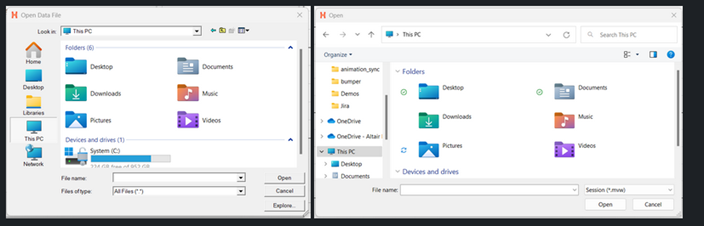
File > Open/Save dialogs and Message dialog:
There are inconsistencies seen in the appearance of the following
types of dialogs:
File > Open
File > Save
Message dialog
Based on the available file extension filters in the File > Open/Save dialogs, and how those dialogs or a message dialog
are opened, the appearance/style of the dialog can differ from other
instances of those dialogs.
Additionally, some of these dialogs can go behind the main
application when you click elsewhere in the application, requiring
you to bring them back to the foreground or reposition the
application.
Example showing the different versions of the File > Open dialog:Figure 20.
The HyperMesh session can freeze if you open the File
menu while the Import Options dialog is launching (but before it is
displayed). If this happens, switch to another application and then return
to HyperMesh to resolve the issue.
When HyperMesh is launched by double-clicking on a session (MVW) file with
multiple pages, in some cases, not all pages will be present in the
HyperMesh session. To avoid this, launch HyperMesh via the Start menu or
command line and load the session file from within HyperMesh via the GUI
(menus, ribbons, and so on) or drag/drop.
Occasionally, a new page created using the Session Browser context menu,
accessed by right-clicking on a page in the browser tree, is not reflected
in the page navigation tool. This can be avoided by creating new pages using
the page navigation tool or by ensuring that the browser context menu used
to create the new page is accessed via right-clicking on blank space within
the browser tree area.
In dark theme, thick white lines are seen between windows in multi-window
layouts.
In multi-window layouts, longer guide bars may be truncated. If this
happens, resizing the graphics area to be wider, or expanding the window so
that the guide bar is able to draw completely when it's accessed, resolves
the issue.
On Linux, if a post client (HyperView, HyperGraph, MotionView, and so on) is
closed with the Session Browser closed, an application error is seen upon
relaunch and the Session Browser will not draw properly. Clicking through
the error messages, closing the browser, and reopening it via the
View menu resolves the issue.
In some cases involving multi-monitor setups, if a browser or dialog is
dragged from one monitor to another, associated context menus can appear
outside the browser/dialog, potentially even on the original monitor.
When running in a NICE DCV environment, there are drawing issues with the
Toolbelt and Advanced Capture when using older versions of NICE DCV.
After switching from HyperMesh to one of the post clients (HyperView,
HyperGraph, and so on), certain function keys not used as shortcuts in the
clients can either display a HyperMesh secondary ribbon with blank icons or
move out of the idle context. If this happens, switching to a context
available within the client and then exiting the context resolves the issue.
Message Center messages are still displayed, even if Show pop up
messages is set to Never in the
Preferences dialog.
When the HyperMesh client API (in other words, Model methods) returns an
error, an extra error message is printed in the console: OSError:
source code not available.
It is not possible to increase/decrease the font size in the Python Console
using Ctrl+scroll wheel; instead, use Ctrl++/Ctrl+-.
When trying to use Ctrl+c to copy selected text in Altair CoPilot, a
floating panel appears instead. To copy text, right-click on the selected
text and select Copy from the context menu.
When cutting a page from the Session Browser or performing the action via
the page navigation tool context menu, a message is displayed, indicating
that the HyperMesh window and its data will be discarded. This is
misleading, as the page has been “cut” instead of deleted. It can be pasted
and therefore, the data has not been discarded.
Geometry
New Features
Sketch
The Image Plane tool has been added, which supports importing JPEG, PNG,
BMP, GIF, and TIFF files to create sketches with tracing.
The Slots tool has been added for creating slots using various
methods.
Enhancements
Sketch
New spline algorithms with local interpolations are now supported.
The Offset tool now supports offsetting splines and ellipses.
The *sketch edit command has been enhanced to create/update/delete
different types of sketch indicators.
The performance of realizing lines/surfaces for large models has been
improved.
Ruled Tool
The Ruled tool now supports surface/mesh creation between lines and
nodes.
The Ruled tool nodes selection has been enhanced to accept close loop
selection.
Topology
The auto color mode option has been added for topology tools.
The Project tool now supports projection of topology points.
Import Updated CAD Files
Importing updated CAD files now uses the option from hm_getoptions.
Copy and Paste Lines from an FE Geometry Surface
Copying and pasting lines from an FE geometry surface is now
supported.
Resolved Issues
Issues with numeric precision truncation in the geometry and meshing tools
have been fixed.
The Ruled tool connectivity issues have been fixed for various combinations
of CAD and FE geometry.
The robustness and performance have been improved for the Ruled, Patch,
Stitch, and Cross Extend tools.
Sketch: performance issues with realizing lines/surfaces for large models
have been resolved.
Sketch: issues with parametric section, linear pattern, and updating
intersection plane have been fixed.
Meshing
New Features
Solid Topology Editing
Automatic mesh update is now available for CAD + mesh and FE geometry
when topology editing 3D solids.
Solid topology editing is now supported for the following:
3D tetra mesh and 3D tetra mesh with a 2D skin
First order for CAD + mesh and FE geometry
Second order CAD + mesh
Solid topology editing now requires full association of the nodes to the
geometry.
Enhancements
Box Trim
The overall performance has been improved.
Mesh quality has been improved at trim boundaries.
Box calculation has been optimized for accuracy.
Handling of 1Ds and solid elements at box trim boundaries has been
improved.
Midmesh
Automatic midmesh extraction now assigns attributes to midmesh surfaces,
which enables faster alignment and easier cleanup.
The following new alignment methods have been added for more efficient
midmesh adjustments:
Middle
Edge Align
Plane
Cylinder
Offset
Fuse
Copy
FE Geometry
Curvature based is the new method to generate topology from FE geometry.
It uses curvature analysis to detect and trace surface features by
evaluating how sharply the model bends. Areas with low curvature are
treated as flat, while high-curvature regions are examined using
principal directions to generate smooth, meaningful lines. It is
controlled by three options:
Edge feature angle
Vertical filter
Parallel filter
Resolved Issues
Some bugs were resolved which has improved meshing compatibility with
embedded 1Ds.
Some bugs were resolved which significantly enhanced the performance of
Element Quality Color mode.
Model Build
New Features
Features Support in Part Representations
Features are now stored directly in part representations.
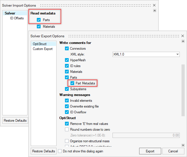
HyperMesh Part Metadata Support on Solver Deck Import/Export
Part metadata can now be optionally imported and exported with solver
decks.Figure 21.
Representation Overlay
The Representation Overlay feature can be used to superimpose a second
representation as an overlay onto a current (session’s) representation
and inspect their differences.
Subsystem Configuration Table View
A new view has been added that provides a clear overview of included and
excluded subsystems within a configuration. This makes the creation and
the management of configurations easier.
Seamless Data Management - Save to PDM
Seamless Data Management – Save to PDM is now supported for subsystems,
making it easier to manage and organize complex assemblies.
Enhancements
PDM Live
Support has been added for query pagination, enabling efficient handling
of large query results.
Parts
The Delete part contents option has been reintroduced when deleting
parts.
Curves and tables associated with properties, and materials defined via
property attribute tables, are now retained in part
representations.
Composite Entities in Part Representations
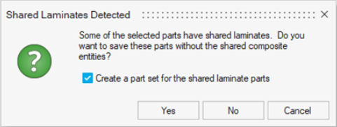
A warning has been introduced when shared laminates across parts are
detected.Figure 22.
Subsystems
Subsystem instancing has been improved with the introduction of the
Instance Sync and Instance Break options.
Library
Curves and failure criteria are now saved along with material to the
local material library.
New commands for library-related actions have been introduced both in
TCL and Python.
Property and Component ID Logic
In models where the PDM PID is not assigned, the component and property
IDs auto-generated during creation of representations are now assigned a
value of Part ID x 10. This allows for more independent ID assignment
and avoids most cases of ID clashes that can occur with multi-thickness
parts.
Model Update
Reports, tables, and naming conventions have been improved to provide
clearer information and facilitate easier interpretation of
results.
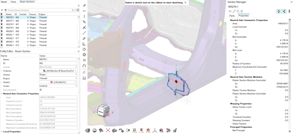
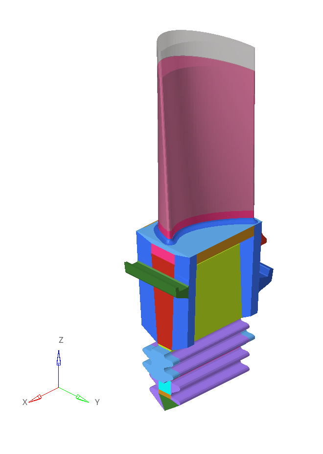
Section Manager
HyperBeam has been fully replaced by Section Manager. The benefit of
using Section Manager is the direct access to the actual model and the
ability to see section updates in real time.Figure 23.
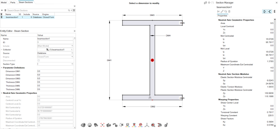
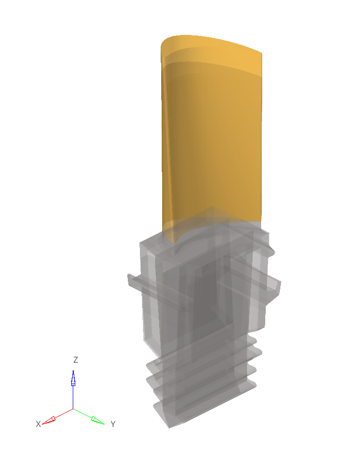
Section Manager now supports all section types. All sections are now
sketch based and sketches are automatically absorbed if read in from an
external source.Figure 24.
The new Disconnected attribute has been added to the Beamsection entity.
This is critical for error checking sections that are open by filtering
and reviewing sections in browser. Error check captures warping function
and shear center computations.
Model Verification
New Features
Manufacturing Check
The Manufacturing Check option has been added to the Verification
Browser. Manufacturing Check detects the following issues on sheet metal
CAD parts:
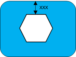
Nut bolt seating surface
Stud seating surface
Electrode interference
Spot weld surface area
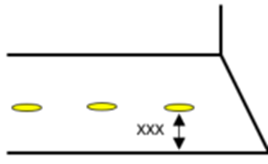
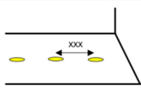
Spot weld pitch
Spot gun interference
Arc weld torch interference
Fillet radius
Trim line radius
Hole pitch
Hole size
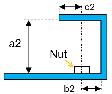
Hole size of nut bolt
Corner radius of oblong designed hole
Distance trim line hole end
Part interference
The detected issues are summarized in a PowerPoint file.Figure 25. Nut bolt seating surface Figure 26. Stud seating surface Figure 27. Electrode interference check Figure 28. Spot weld surface area Figure 29. Spot weld pitch Figure 30. Spot gun interference Figure 31. Arc weld torch interference Figure 32. Fillet radius Figure 33. Trim line radius Figure 34. Hole pitch Figure 35. Hole size Figure 36. Hole size of nut bolt Figure 37. Corner radius of oblong designed hole Figure 38. Distance trim line hole end Figure 39. Part interference
Enhancements
Support for 3DXML data in all functions.
You can now read material, thickness, and weight from 3DXML data.
"Import ANSA comments" can be controlled from a configuration.
Select "ON/OFF all" simultaneously checks items in the configuration file
(spot weld, connection, and manufacturing checks).
Material ID or Name is now displayed in the Comparison Excel report.
Assembly image slides for 0-30, 30-90, and 90-100% are added to see all the
partial, unmatched assembly images.
Partial Meshing Patch Area% is now configurable with a configuration
file.
The Comparison "AI-approach" option is improved to find the closest part
first, followed by the surrounding parts.
The Model Build function extracts a connector from stud and NUT CAD data,
similar to bolt.
The MBLD Match function aggregates a 3D solid from a base surface if it is
in a single part.
Resolved Issues
Comparison for multiple variant parts points to the same source in the
comparison.
Comparison Report button: Click opens an old
PowerPoint report.
Comparison in partial mesh: Free edges were seen in the partial mesh
output.
Comparison in partial mesh: Session occasionally becomes unresponsive during
a partial mesh.
Python file: Error appears in a network installation.
User profile: Sets the correct profile for comparison for the selected FE
input file.
Morphing
New Features
New Shape Visualization
Shapes are now drawn as transparent mesh instead of vectors.
When you create a shape, a transparent mesh is drawn, which corresponds
to the perturbation of each node associated with that shape. The
transparent mesh signifies the position of each node after applying the
shape.Figure 40. Figure 40 shows an example of a shape drawn as transparent mesh on screen.
Review Shapes
Shape entities can now be reviewed by activating the Review (Q)
functionality. Shapes will be drawn with the highlight color when in
Review mode and everything else will become transparent. This is
especially useful when examining shapes that are inside the original
mesh.Figure 41. Figure 41 shows an example of a shape in Review mode (Q).
Important: Any nodes that move less than 5% with respect to the maximum node
movement associated with that shape will not be drawn on screen as
transparent mesh. This is done to focus the shape visualization on
the moving nodes and to increase performance for shapes that
encompass the whole model (for example, morphing with kriging and
volume morphing).
Enhancements
Miscellaneous
Morph constraints can now be created by selecting FE geometry
surfaces.
The Morph Constraint ON option now supports selecting multiple
surfaces.
Free Morph: the automatic population of anchors and morph area is now
triggered each time the Automatic check box is selected.
Performance Improvements
Record Shape: performance has been improved.
Proximity Morph: interactive morphing is significantly faster when you
morph with nodes, faces, or edges. The effect is more profound with
bigger models.
Volume Morph: performance has been improved when creating 10.000 or more
volumes using the sweep method.
The performance has been improved when mapping to geometry.
Resolved Issues
The Non-Linear Explicit morphing method now works properly.
The Linear Static morphing method now works properly.
Models no longer occasionally crash after remeshing post morph.
Models no longer occasionally crash after deleting morph volumes.
Models no longer crash after mapping elements to lines using the kriging
method.
PhysicsAI
New Features
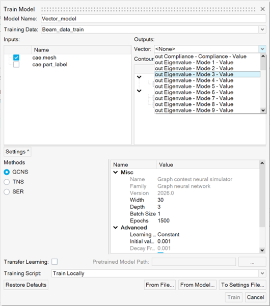
Automatic Vector Extraction
PhysicsAI can now automatically parse vector data contained in
.out or .pch files with
the same name and stored in the same subdirectory as the
.h3d files used during dataset creation.Figure 42.
Depending on the file extension used, the nomenclature used for the
extracted vectors is out {Type}–{Requests}-{Components}
or pch {Type}–{Requests}-{Components}.
Enhancements
Migration to Pytorch
PhysicsAI now uses Pytorch. All the required libraries are packaged as
part of the installation. GPUs are automatically detected and used.
Batch Utility Moved to Common Components
On Linux, the location of the batch utility has changed from
<install_location>\hwdesktop\hw\eds\linux\edspy.sh
to
<install_location>\common\eds\linux\bin\linux\edspy.sh.
On Windows, the location has changed from
<install>\hwdesktop\hw\eds\bin\win64\edspy.bat
to
<install_location>\common\eds\win64\bin\win64\edspy.bat.
Plots
Enhancements
Plotting enhancements:
From the Results Browser context menu, use the Plot
Control option to plot charts.
Create charts through the graphical selection of nodes or elements.
When saving a session, an option has been added to save chart layouts.
Chart Manager enhancements:
You can now plot derived load cases.
Multiple windows and pages are dynamically supported during plotting.
Axis labels are now available when plotting charts.
For the Direct Input table input type, copy-paste functionality has been
added for columns.
HM tables, in addition to the existing support for Matrix Browser tables,
are now supported.
Performance enhancements have been made to handle a larger number of
charts.
Resolved Issues
Issues with the Chart entity.
Known Issues
The following known issues will be addressed in a future release:
The Chart entity is only supported in the Abaqus, ANSYS, Nastran, and
OptiStruct profiles.
Post
New Features
Abaqus Ply Matching for Composite Post-processing
Ply matching allows for effective post-processing of composite results,
as particular plies can be selected consistently instead of looking at
section point results, which might involve different plies for the same
section point. The naming convention includes:
Plyname_TOP/MID#/BOT for composites
SHELLLAYERS_TOP/MID#/BOT for metallic shells
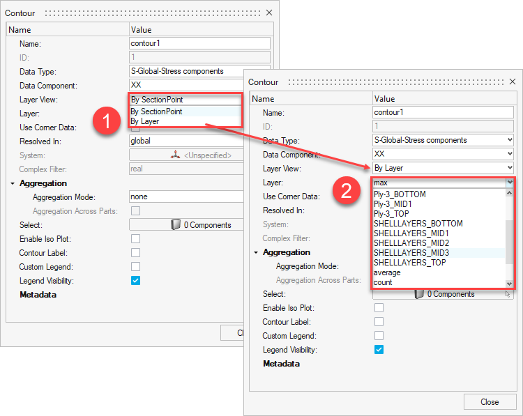
Plot Controller Workflow
The Plot Controller workflow now includes the options to switch between
“By SectionPoint” (traditional option) and “By Layer”.Figure 43.
Result Query and Matrix Browser Support
The Result Query and Matrix Browser are now supported via a new option
in the Preference dialog. From the File menu, select Preferences > HyperMesh > Post > Organize Abaqus SectionPoint by model layers.
Enhancements
Random Response Dialog
Support for the following interfaces and result files have been
added:
Nastran: OP2, XDB
Abaqus: ODB
ANSYS: RST
An option has been added to use charts (only from direct input) and curves
created in a HyperMesh session as PSD curve inputs. To access this option,
go to the Random Response dialog > Input PSD Curve From > Curve or Chart
Default file location for the input files of the model file if the model
file is imported in the session.
A filter has been added to sort by name or ID in the Subcase and
Results dialog.
4K resolution dialog enhancements have been added.
Safety Report Manager
New Features
New Modules
EuroNCAP FAR Side Occupant Assessment.
ADR Description (part of Seat load cases).
ISOFIX (part of Seat load cases) is now available.
New Features in Existing Modules
Injury metrics for Humanetics Body Model (HBM-Connect) as part of
Front impact - EuroNCAP regulations.
The Frontal impact > IIHS > ODB module now supports:
Second row left occupant injury calculations.
DIAdem files for physical test data.
Contour Plot module is enhanced to support FLD plot creation.
Contour Plot module can now create Derived Results on demand and
apply them as a contour.
General New Features for the Safety Report Manager
Perform curve comparison across multiple iterations (CORA
tool).
Append or Overlay the results and the slides in the PowerPoint PPT
report during the overlay scenario.
Apply user-defined reader settings while loading the Radioss and
LS-DYNA results.
Run custom scripts within the framework.
Enhancements
Contour plot and Animation: New modules are updated to read and apply custom
legend styles.
A new HyperGraph default file is now supported specifically for an overlay
scenario. It allows you to control the curve legend attributes, such as
visibility and legend position, during the overlay process.
A new HyperView default file is now supported specifically for an overlay
scenario. It allows you to control the curve legend attributes, such as
visibility and legend position, during the overlay process.
Postscript functionality is enhanced with a new option to change the line style
per layer from the session files loaded in HyperGraph.
Luggage Retention module is updated to capture animations (MP4 format) when
generating the report.
Loadcase Description module is updated to take additional inputs for Pulse/Load
and Dummy/Test equipment.
Energy Dissipation module is enhanced to include a summary table for each run
containing Clip 3ms and 80g values.
Supports DIAdem (*.dat) files for physical test data.
Time step information is now displayed in all animations slides.
Resolved Issues
Contour plot > Effective Plastic Strain missing layer information issue.
PPT slide titles not aligned on the left.
Plotting pulse curves for seat load cases.
Tracking system settings in the Measure Plot module.
Element selection issue in the Energy Dissipation module.
The Excel limitation of 32767 characters per cell when saving the Safety Report
Manager configuration file has been resolved.
Known Issues
The following known issues will be addressed in a future release as we continuously
improve the software:
Input validation check is not supported for Battery Section Force and BOM
modules.
Load Path, Run Statistics, and Weld Failure modules, as well as input
validation check functionality, is not supported for Radioss and PAM-CRASH
solvers.
Safety Tools
New Features
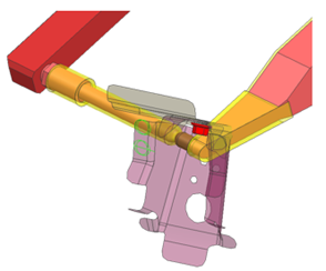
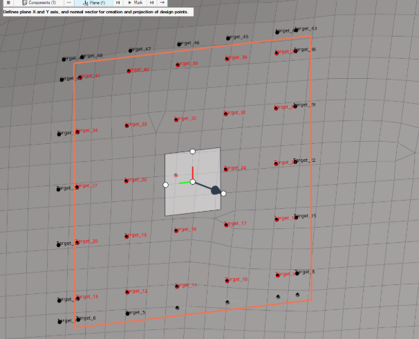
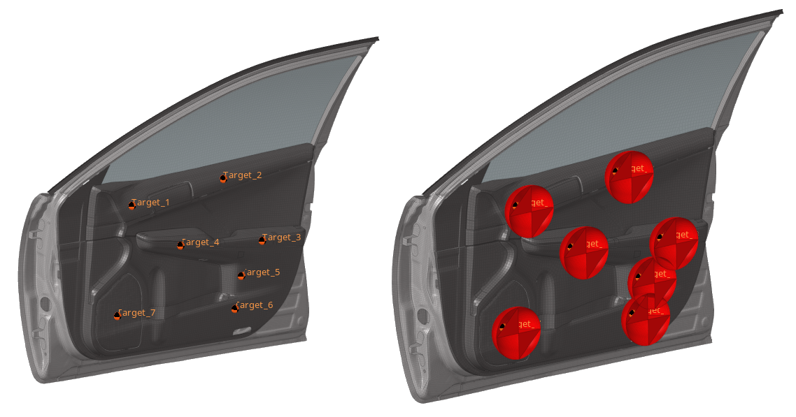
Generic Impact Workflow
This tool is available in Radioss, LS-DYNA and PAM-CRASH profiles, allowing:
The definition of impact points on any type of structural parts.
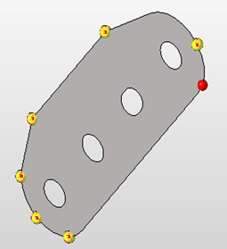
The creation of impact points can be done by three different methods:
Manual selection of locations on the graphic.
Import of impact locations defined in a
.csv file.
Automatic creation of a raster or grid of points on a
user-defined plane and projection on the surface to
impact. For example:Figure 44.
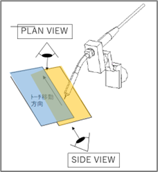
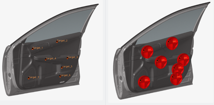
The automatic positioning of any type of impactors following one
of the positioning logic Normal to Target or Target/Angles.
The automatic export of ready-to-run solver decks. The logic of
export of the solver decks follows the same logic used in other
Safety Tools such as the IP Impact tool.
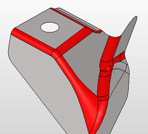
The example below
shows multiple impact simulations on a door-trim using a
spherical impactor:Figure 45.
Enhancements
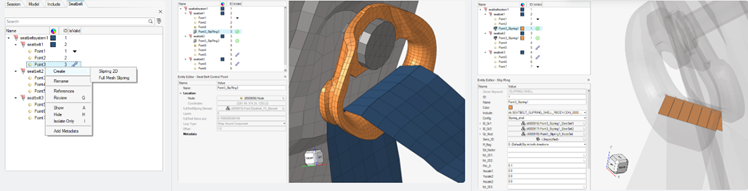
Seatbelt Tool
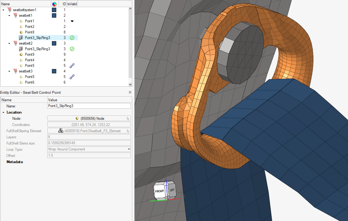
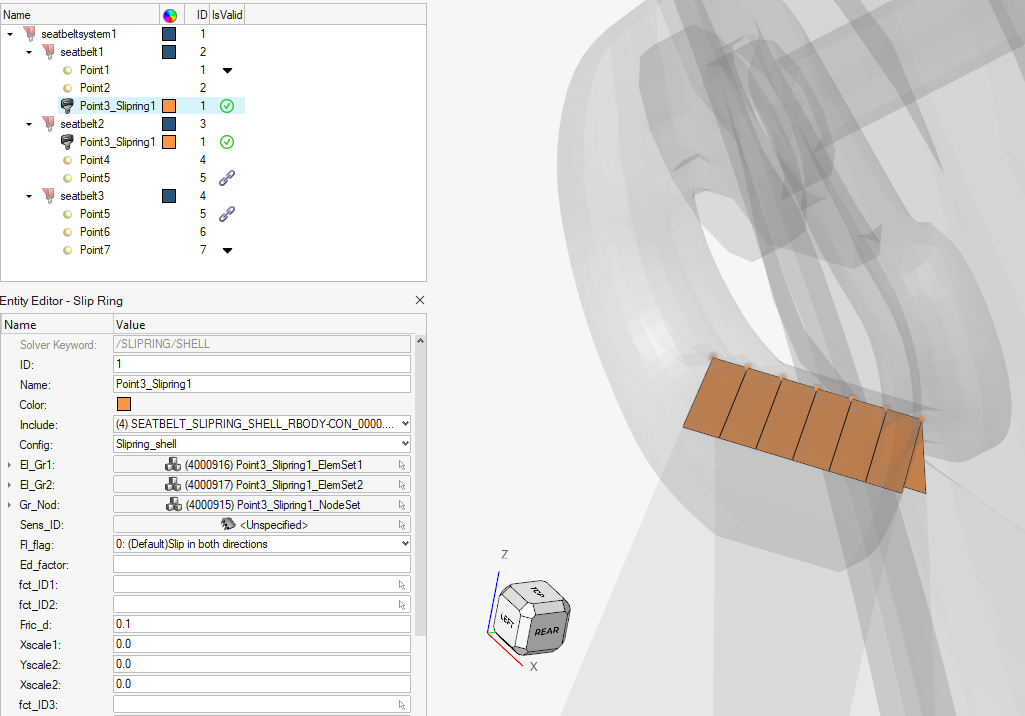
Radioss profile: Creation of /SLIPRING/SHELL is now available from the
Seatbelt tool via the Slipring 2D context menu option on control
point.
Radioss, LS-DYNA and PAM-CRASH profiles: Creation of full-meshed
slipring is enhanced, using an embedded simulation for robust and high
quality results.Figure 46.
Resolved Issues
IP Impact Tool: CSV files are now correctly exposed for selection for the
creation of points with Testlab method.
Skeleton Modeling
Enhancements
Auto-Offset Tool
The Auto-Offset tool now supports Member Joints input.
Member Creation and Absorb
Member Creation and Absorb now generate sections perpendicular to the
line profile.
Joint Creation Performance
Joint creation performance has been improved when geometry is the
input.
Skeleton Environment Workflow Help
The workflow help has been improved within the Skeleton
environment.
Resolved Issues
The crash while performing line extract with a small resolution has been
resolved.
The slowdown when entering the Absorb tool has been resolved.
The crash when using Section Cut with the Section Cleanup option enabled has
been resolved.
Deleting multiple joint legs in a single operation no longer deletes the
related elements.
Solver Conversion
Enhancements
Abaqus to OptiStruct Conversion
CLOAD(MOMENT), when referred to the local coordinate system (LCS), is
converted to MOMENT.
LS-DYNA to OptiStruct Conversion
ELEMENT MASS PART is converted to NSML.
SECTION SHELL is converted to PSHELL(Explicit).
Ansys to Abaqus Conversion
Material Plastic Strain is converted to *PLASTIC.
Task Manager
No updates were made to the Task Manager for 2026.
CAD and Solver Interfaces
Abaqus Interface
New Features
New context support for creating rigids and RBE3s.
Enhancements
The pre-tension section in a group entity now allows you to select and
define a follower load option.
A new model checker has been added to detect long names (beyond 80
characters) for solver-named entities.
Introduced the selection of a property when creating a set segment with
*SURFACE, TYPE=ELEMENT. This allows you to create set segments based on the
element set used for property definition.
Resolved Issues
The Entity Editor has been improved for the Abaqus beam element.
The Surface Interaction keyword is no longer visible in the Property entity
for Abaqus/explicit.
Set segment normal was reversed upon Import/Export in the Abaqus 2D
profile.
Transformation of a nodal DOF using sets now works properly.
Issue with the API not creating a distribution table and orientation.
ANSYS Interface
Enhancements
RMODIF Card Supported
Support for reading modified real constant sets.
DMOPT
Supported in the load step entity.
RSTCCONTROL
Controls whether element single value results are written to the results
file. This is supported within the OUTRES card in the load step
entity.
SOLOTION
Specifies solution transition options. This is supported in load step
entity.
RSOL and MISC
Supported as part of the OUTRES card in the load step entity.
RESCONTROL
Controls file writing for multi-frame restarts.
Analysis Cards Moved
Analysis cards from control cards have been moved to the load step
entity based on analysis type.
From the Geometry Import Options dialog, choose
between two reader options, NX (third-party) and
NX (native), when importing NX files, giving
you greater flexibility.
Broader CAD Support
Support added for Autodesk Inventor 2026, Siemens NX 2506 via native
readers, Siemens NX2412 via third-party, CATIA R35, and SOLIDWORKS
2025.
Stronger 3DEXPERIENCE Integration
Enhanced support for 3DEXPERIENCE 2024x ensures smoother workflows with
the latest platform updates.
Enhancements
Faster Imports
Performance issues with certain CATIA V5 files have been resolved for a
smoother experience.
Improved Reliability
Fixed import issues affecting certain CREO files.
Up-to-Date Technology
Upgraded to the latest ODA libraries (v26.2) for improved compatibility
and performance.
Overall Optimizations
General performance improvements across the platform.
CAD Import Options
Added support for setoption and
hm_getoption with persistence throughout the
session.
LS-DYNA Interface
New Features
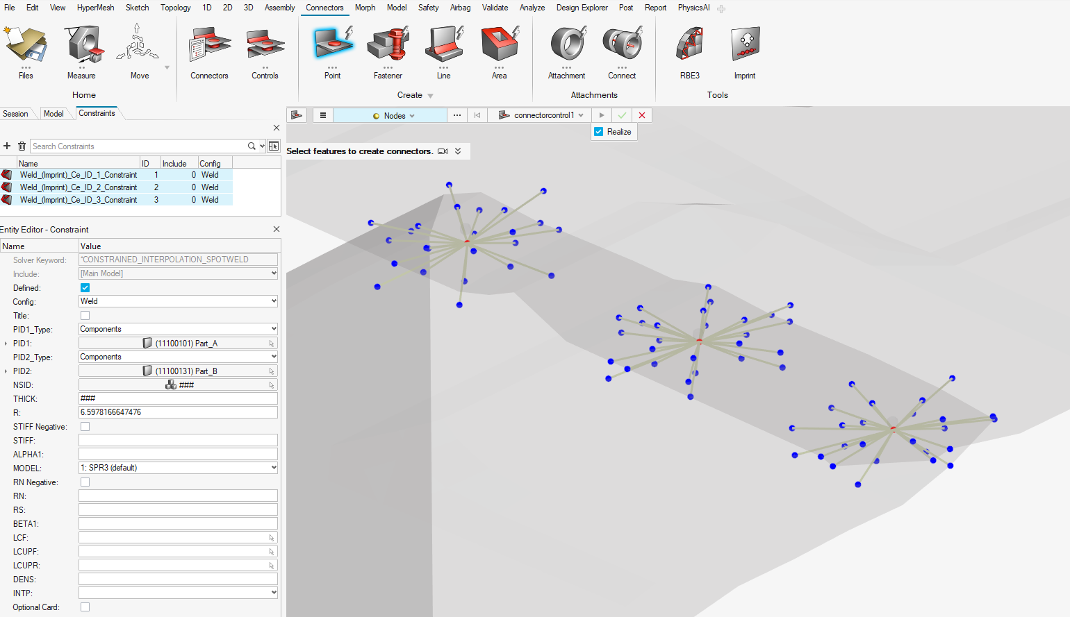
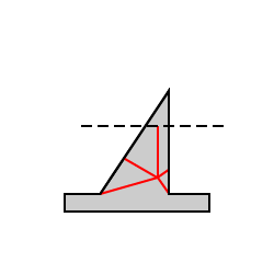
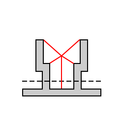
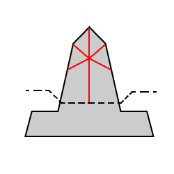
CONSTRAINED_INTERPOLATION_SPOTWELD
CONSTRAINED_INTERPOLATION_SPOTWELD is now available as a point connector
type, which supports absorption, imprint, and realization.Figure 47.
New Generic Impact Workflow
The new Generic Impact tool has been added, which you can use to define
impact points on any type of structural parts, automatically position
any type of impactors, and automatically export ready-to-run solver
decks. For more details, see the Safety Tools release notes.
Example: Figure 48 shows multiple impact simulations on a door-trim using a spherical
impactor.Figure 48.
Enhancements
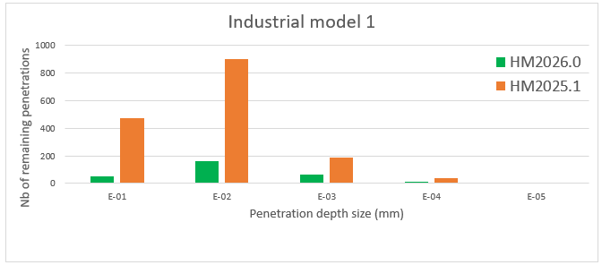
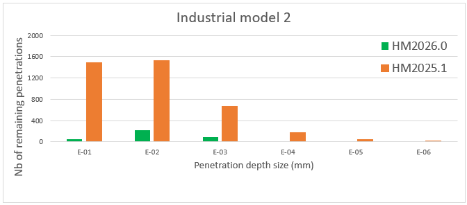
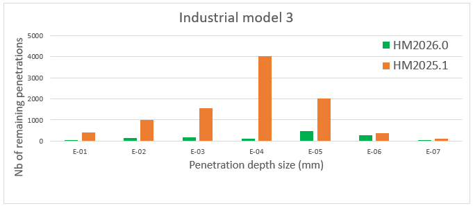
Contact Penetrations Check Tool
Enhancements have been made in penetration calculation accuracy for
SOFT=2 (segment based) contacts and depenetration process performances.
The graphs in Figure 49, Figure 50, and Figure 51 show the drastic reduction of remaining penetrations after the
depenetration process for contact SOFT=2 for different large industrial
models within HyperMesh 2026.0 compared to HyperMesh 2025.1.Figure 49. Figure 50. Figure 51.
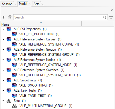
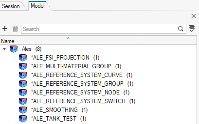
ALE Keywords Mapping
LS-DYNA ALE keywords are now all mapped into a single entity, and no
more than eight different entities, for cleaner model organization and a
simplified future of ALE keywords support.
Figure 52. HyperMesh 2025.1
Figure 53. HyperMesh 2026.0
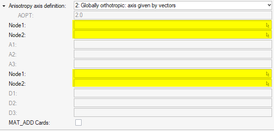
Enhanced Material Anisotropy Definition for All Anisotropic
Materials
Node selection is no longer required to define (X1,X2,X3), (A1,A2,A3),
(D1,D2,D3), or (V1,V2,V3) anisotropy axis. It is now directly driven by
location selection or direction selection. You can also input each
attribute value manually in the Entity Editor.
Figure 54. HyperMesh 2025.1
Figure 55. HyperMesh 2026.0
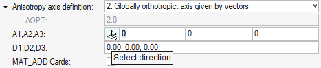
New Keywords Supported
Support has been added for the new AIRBAG_CPG and
DEFINE_CPG_GAS_PROPERTIES keywords.Figure 56.
Enhanced Keywords
The new RESTRT and METHOD attribute values have been added in the
FREQUENCY_DOMAIN _ACOUSTIC_BEM keyword.
The new SUBCASE option has been added in the FREQUENCY_DOMAIN_FRF
keyword.
The new TITLE option has been added in the CONSTRAINED_SPR2 and
CONSTRAINED_INTERPOLATION_SPOTWELD keywords.
Seatbelt Tool
Full-meshed slipring creation has been enhanced using an embedded
simulation for robust and high quality results.Figure 57. Figure 58.
Resolved Issues
In SECTION_BEAM, when the QR attribute is blank or equal to 0.0, the value
is now maintained on export and not automatically switched to 2.
When creating CONSTRAINED_INTERPOLATION, the default value of independent
DOF is now set to 1.
In specific cases, the segmentation error when reading INITIAL_STRESS_BEAM
has been fixed.
Nastran Interface
New Features
Rigids/RBE3s context workflows have been added.
Resolved Issues
BCPARA AGUMENT contains an incorrect description in the Entity Editor.
Mass calculation was incorrect for elements defined with PSOLID and
MATORT.
Unable to read some HyperMesh comments correctly from BDF files.
OptiStruct Interface
New Features
Rigids/RBE3s context workflows have been added.
Piezoelectric analysis support.
Enhancements
Model check enhancement to check missing MSID or SSID on TIE bulk card
definition.
Resolved Issues
DRESP1 for buckling response type export was incorrect.
Incorrect property assignment to CROD elements.
Incorrect import of NLCTRL bulk card definition.
PAM-CRASH Interface
New Features
PAM-CRASH Sets (Group keyword) Migrated to the New Infrastructure
This migration allows you to create and edit sets quickly and
efficiently.
The Group keyword set can be directly created without needing to
create ‘set of sets’ selecting entities.
Multiple Sub objects can be referred to the Group keyword with
different types of entities.
Range selection without upper and lower bounds has been
implemented for sets containing nodes, elements, and parts.
SEG and EDG are mapped to the Set Segment.
New Generic Impact Workflow
Use this tool to define impact points on any type of structural part,
automatically position any type of impactor, and automatically export
ready-to-run solver decks. For more details, see the Safety Tools release notes.
Enhancements
Penetration check with solver output functionality has been extended to
implicit solver output, which uses the IRMV=-2 option in contact for
adjusting local contact thickness. Support for reading the solver output of
contact type 43 (edge-to-edge) has been added.
The new keyword Multi-Block Contact Input is now supported.
Seatbelt Tool
The Full-Mesh Slipring option, which is accessible from the Seatbelt Browser > Create context menu, has been enhanced to use an embedded
simulation for robust, high-quality results.Figure 59.
Resolved Issues
Modular parts MPART/ are now selectable in a penetration check embedded
algorithm for checking penetrations and intersections.
Inconsistent extra space in GRP names.
Group keyword order is now maintained in the solver deck.
Previously, when importing RUPMO type 11 with a blank space, FILTER=CYCLE
was automatically added. This has been corrected. The blank space is now
preserved during import and remains blank upon export.
Export issue for MAT Type 143 has been corrected when the optional card ‘OSR
and NDP’ is selected and FILTER, INTERP attributes are set to blank.
Issue with set loosing component selection upon importing an include file
with $HMCOMP comment with same ID.
Radioss Interface
New Features
New Radioss 2026 Profile
A new Radioss profile has been added for 2026.
New Generic Impact Workflow
The new Generic Impact tool can be used to define impact points on any
type of structural parts, automatically position any type of impactors,
and automatically export ready-to-run solver decks. For more details,
see the Safety Tools release
notes.
For example, Figure 60 shows multiple impact simulations on a door trim using a spherical
impactor.Figure 60.
Enhancements
New Keywords Supported
The following keywords are now supported: /FAIL/FRACTAL_DAMAGE and
/GAUGE/POINT.
Enhanced Keywords
The following keywords have been enhanced:
The Icontrol attribute has been added in the following keywords:
/DEF_SOLID, /PROP/TYPE6, /PROP/TYPE14, /PROP/TYPE20,
/PROP/TYPE21, and /PROP/TYPE22.
New Ifail_so values have been added in /FAIL/JOHNSON.
A new Istrain value has been added in /FAIL/FLD.
A new Pmin attribute has been added in /MATLAW2.
A new Ip=26 attribute value has been added in /PROP/TYPE9,
/PROP/TYPE10, /PROP/TYPE11, and /PROP/TYPE16.
RbodyIDs in /PROP/TYPE15 is now a node selector.
The Main_ID2 attribute has been added in /INTER/SUB.
The output variable names in /TH/CLUSTER have been
corrected.
New Irem_gap and Irem_i2 attributes have been added in
/DEFAULT/INTER/TYPE19.
A new Inacti value has been added in /INTER/TYPE24.
New output variables VX,VY, and VZ have been added in /TH/PART
and /TH/SUBS.
The number of mue and alpha attributes have been increased to 10
in the definition in /MAT/LAW42.
The new Seed attribute has been added in /FAIL/ALTER.
The Tension attribute has been updated in /MAT/LAW88.
A new Ikin attribute and Iflag value have been added in
/MAT/LAW87.
Multiple new attributes have been added for compaction mode in
/MAT/LAW50.
/MAT/LAW2 is now selectable in /MAT/LAW51.
The material selection filter has been updated in /PROP/TYPE11,
/PROP/TYPE16, /PROP/TYPE19, and /PLY to allow the selection of
all compatible material models.
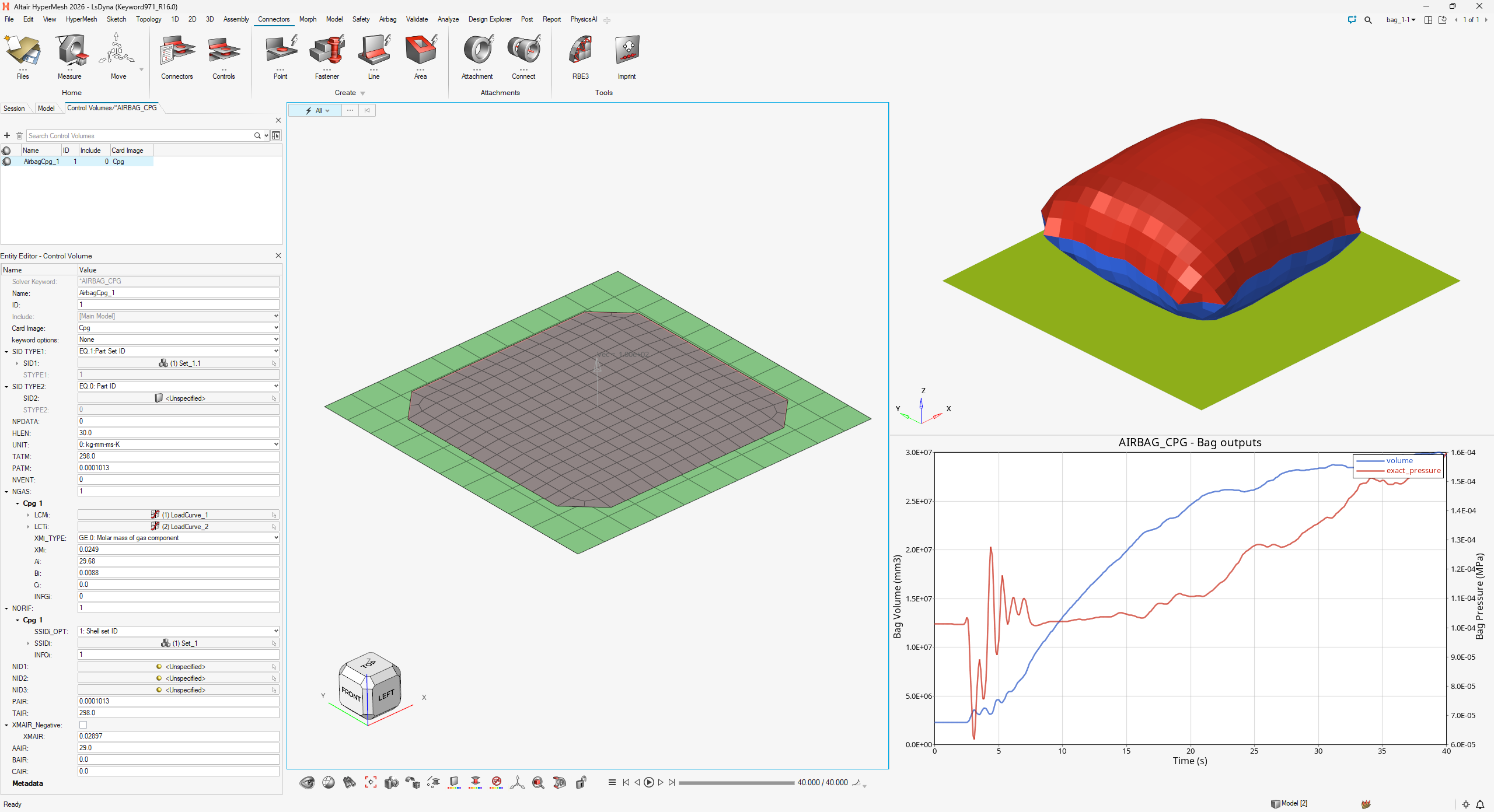
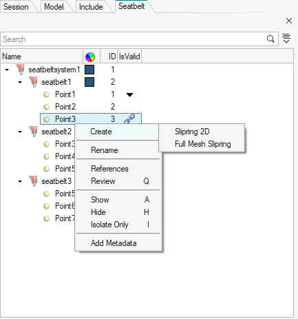
Seatbelt Tool
Creation of /SLIPRING/SHELL is now available from the Seatbelt tool.
Right-click the control point and select Slipring
2D from the context menu.
Creation of a full-meshed slipring has been enhanced using an embedded
simulation for robust and high quality results.Figure 61. Figure 62.
Airbag Folder Tool
The following enhancements have been made to the Airbag Folder tool:
New vertical zig-zag folding has been added.
New diagonal tuck folding has been added.
New rolling folding has been added without the usage of a
rolling-tool model. Instead, it is driven by user inputs on the
tool shape.
The method to define opening in tuck folding has been
improved.
Z-translation for simple fold and rolling has been added.
The definition of rigid regions for inflator insertion has been
enhanced.
Resolved Issues
Solvermasses defined on a set of assemblies are now correctly considered in
mass/COG/MOI calculation.
The termination time value generated by the Engine File Assistant has been
corrected.
/FRICTION keywords are no longer detected as unused.
String length to define the stress file name in /STATE/STR_FILE has been
corrected to a maximum of 100 characters.
At the end of the Bus Rollover workflow, the curve defining the gravity load
is now correctly assigned to the /GRAV keyword.
Common Interfaces
Enhancements
Model Checker
A new “Shared laminates” check has been added, which checks if there are
any laminates shared among parts and displays a warning that lists the
shared laminates.
 icon.
icon.