Define Hotspots
Define a nodal hotspot to assign crack properties.
-
Click the Hotspot tool.
Figure 1.  The hotspot guide bar opens. Click on the first sandwich button to launch guidebar options for automatic or manual hotspot creation.
Figure 2. Auto Hotspot 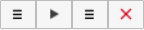
Figure 3. Manual Hotspot  The hotspot guide bar contains the following options:
- Automatic hotspot creation:
Figure 4. 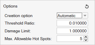
- The following parameters are required to define hotspot clustering:
- Threshold Ratio
- Percentage of the max element damage used to create the required cluster.
- Damage Limit
- Entities with damage less than the damage limit will not be considered in hotspot creation.
- Number of Hotspots
- Number of hotspot clusters to be detected.
- Click on the play button to launch Strain-Life calculation
to automatically identify hotspot locations in the model for
the assigned fatigue events. The max node of each hotspot
will be chosen as the crack location. Note: Strain life evaluation parameters, material selection and fatigue events should be defined prior to identifying automatic hotspots.
- The following parameters are required to define hotspot clustering:
- Manual hotspot creation (default) and configuration file input.
- Node selection for manual hotspot creation.
- Create hotspot after node selection.
- Crack properties at hotspot.
- Automatic hotspot creation:
-
Click the sandwich icon to open the Hotspot creation options.
Figure 5.  Creation option is set to Manual by default.
Figure 6. 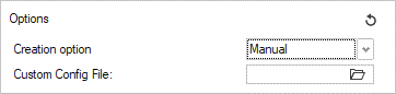 Custom config file allows the user to:
- Create a hotspot at the required node.
- Create-assign a system to define the crack direction.
The feature requires a configuration file (.txt) linked to a .csv file containing nodal information for system creation using three nodes.
Configuration file:Figure 7. 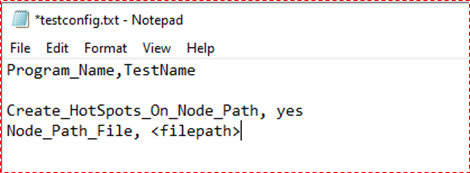 Nodal Path file (.csv)
Figure 8. 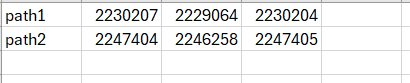
<Path Name>, <Origin node ID>, <Crack Direction node
                            ID / end node ID defining thickness along crack length>, <Stress
                            Distribution plane node ID>
Header information is necessary to define the Stress distribution plane XY/XZ during system creation. The crack direction will always be set to X. If no header is defined in the nodepath file, the system created will always be in X direction and default plane chosen is XZ.
If
Create_HotSpots_on_Node_Path = Yes, hotspot is created at the origin node and listed in Hotspot dialog. -
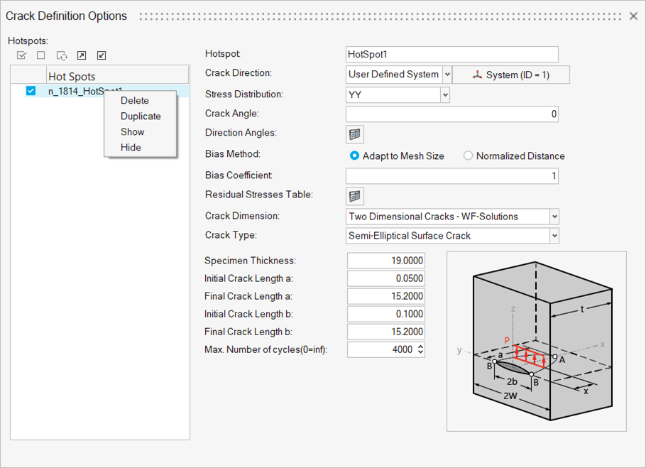
Click the sandwich with dropdown icon to define crack definition options.
Figure 9. 
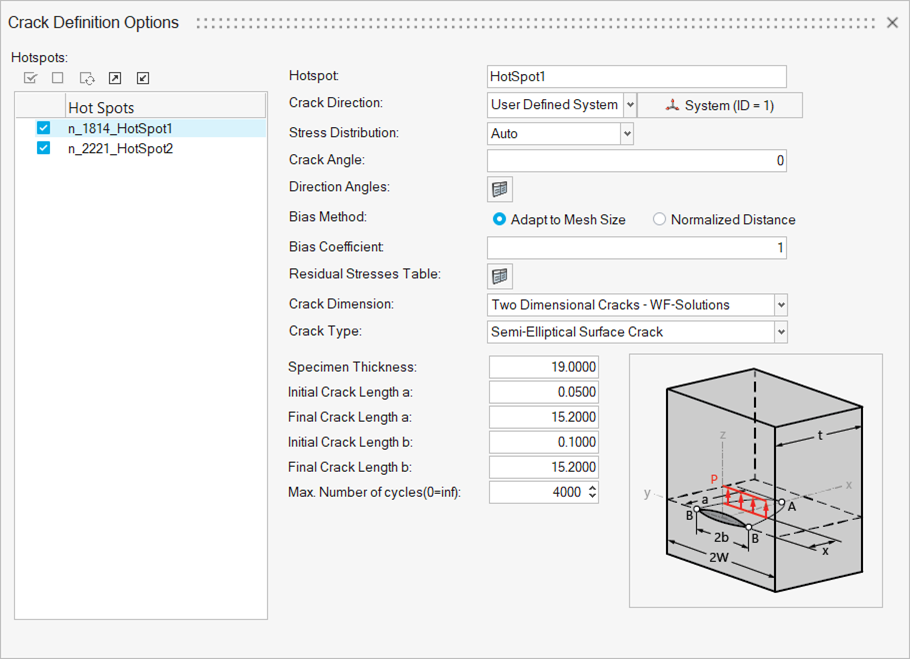
- Crack Direction
- Normal: Surface normal at the selected node across the thickness.
- Stress Distribution
- Stress distribution calculated along the crack direction. Options:
- Auto
- Stress in the XZ plane as per the default system (Default)
- Absolute Maximum Principal
- Absolute max. principal stress in the XZ plane along the crack direction
- YY
- Stress in the XY plane of the defined system
- ZZ
- Stress in the XZ plane of the defined system
- Crack Angle
- Rotation of the stress distribution plane about X-axis (crack direction)
- Direction Angles
- List of angles. Each angle represents an individual crack growth direction to be evaluated. Each direction is defined in the plane of the requested stress combination.
- Biasing Options
-
-
Adapt to Mesh Size: Creates query points across the model thickness along the crack direction considering mesh size.
Bias Coefficient (0 < value <= 1.0)
Along the crack direction, distance between two consecutive stress evaluation points in a mesh is determined by the bias coefficient x minimum distance between centroid and corners.
- Normalized Distance: User-defined normalized distance (0
to 1) file with required biasing along the crack
direction.
Figure 10. 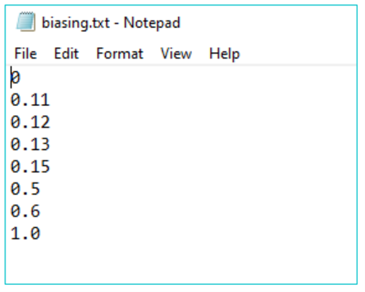
-
- Residual Stresses Table
- Defines the residual stress defined to the hotspot.
-
Import residual stress file in .txt format per hotspot.
Figure 11. 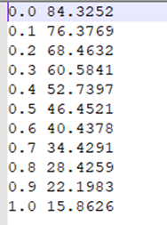
- Crack Dimension
- Supported dimensions are:
- 1D Dimensional Crack – WF solutions
- 2D Dimensional Crack – WF solutions
- Crack Type
- Supported crack types supported are listed in Supported Crack Types.
-
Right-click for more options.
- Delete
- Delete the hotspot
- Duplicate
- Duplicate existing hotspot
- Show
- Show the crack direction of the hotspot
- Hide
- Hide the hotspot direction
-
Select by clicking the check button for the hotspot to be evaluated.
Note: Hotspot properties can be imported and exported via the hotspot .xml file.Note: Multiple hotspot editing is available on drag selection of more than one hotspot.