From the menu bar, click nFX Analysis > Boundary Conditions > Motion.
Introduction
Wall boundary particles can be moved during a simulation with a prescribed motion.
The principal concept is to define a motion for a specific phase/body and apply this
motion within a given time-frame.
Common parameters:
Start Time / End Time
Specifies the start and finish times which define the window where the
motion is active.
Damping Time
This parameter specifies a time window for the acceleration of the body. At
the start time, the motion will ramp up from the body’s initial state to the
specified value over this time. This minimizes pressure fluctuations and
instabilities caused by instantaneous changes in velocity.
Advanced Options
A free text box where additional parameters can be specified.
Motion Types
The following motion types are supported in SimLab. Also,
animation is supported for few of the motions.
Translation
motion_type = IMPOSE_VEL. Defines a translation type motion.
Velocity: Imposed velocity defined as a vector in x, y, z
directions.
Rotation
motion_type = ROTATE_AXIS. Defines a rotation type motion.
Frequency Unit: Rotational Frequency may be defined using revolutions or
radians, per second or per minute.
Initial Frequency: Rotation Frequency at Start Time, usually zero unless
creating sequential motions.
Frequency: Rotation Frequency which will be reached after damping
time.
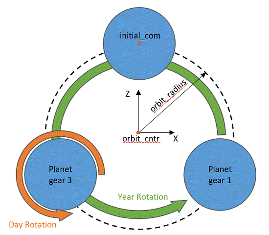
Planetary
motion_type = PLANETARY. Allows definition of planetary gears.
Year: The main orbit of the planetary bodies.
Day: The local rotation of the planetary bodies.
Frequency Unit: Rotational Frequency may be defined using revolutions
or radians, per second or per minute.
Initial Frequency: Rotation Frequency at Start Time, usually zero unless
creating sequential motions.
Frequency: Rotation Frequency which will be reached after damping
time.
Note: Planetary motion is normally
accompanied by a Rotation motion for the carrier.
Figure 1.
Conrod
motion_type = CONROD. Allows definition of a piston and conrod
mechanism.
Note: Conrod motion is normally
accompanied by a Rotation motion for the crankshaft.
Frequency Unit: Rotational Frequency may be defined using revolutions or
radians, per second or per minute.
Crankshaft Axis: Rotation Axis of the crankshaft.
Initial Frequency: Rotation Frequency at Start Time, usually zero unless
creating sequential motions.
Frequency: Rotation Frequency which will be reached after damping
time.
Piston Axis: Piston sliding axis (vector must point towards
crankshaft).
Journal Axis: Location of the conrod journal bearing axis.
Crankshaft Phaseshift: Angle to define Conrod starting position, based
on angle from crankshaft_normal (TDC).
Conrod length: Conrod length between wrist pin and journal bearing
centers.
Piston Offset: Offset distance from the piston centerline to the
crankshaft centerline.Figure 2.
Rigid Body
motion_type = PASSIVE_RIGID_BODY. Defines a 6-DOF rigid body motion for
a body freely interacting with the fluid. Constraints, forces, and
damping are available for each translation and rotation
component.
Coordinate system: If a local coordinate system is defined in SimLab, it can be selected in place of the global
coordinate system. If defined, the motion XYZ parameters use the LCS,
not the GCS.
Mass, Center, and Mass Moment of Inertia are automatically calculated
when a body is picked, using the density from the assigned
material.
Initial velocity specifies the body’s velocity at time = 0.
Constraint System: A local coordinate system can be selected
specifically for the constraint system.
Hinge point: If the body is to rotate around a different point than the
center of mass, the hinge point can be defined (together with constraint
system) to define the motion.Figure 3. For both linear and angular motions, there are nine parameters
each to specify. These parameters are optional and only need to be
specified when needed:
Locked Displacements: When the direction is ticked, the
corresponding DOF will be removed.
Force: Specify an external force acting on the body (for
example, an actuator) in each axis.
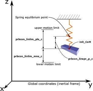
Spring stiffness: Define a spring stiffness resisting
displacement in each axis.
Spring relaxed position: Used when there is pre-deformation of
the spring. This specifies the equilibrium point of the
spring.
Damping: Define motion damping in each axis.
Motion upper/lower limit: These parameters are used to restrict
the range of motion (for example, a hard stop) available in each
axis.
Velocity may be specified in each axis either as a constant, or
by using a time history file (time, X vel, Y vel, Z vel).
Custom
motion_type = POSITION_FILE. Allows import of a time history file to
define any kind of arbitrary motion. The solver will automatically
linearly interpolate between the prescribed position data.
Orientation = false: The input .csv file must be of
column-format time x y z alpha beta gamma where alpha,
beta, and gamma are components of the rotation vector in units of
[rot/s]. The Cartesian coordinates of the first row of the input file
must be 0 0 0, which corresponds to the initial
position of the Center of Mass (COM).
Orientation = true: The input .txt file must be of
column-format time x y z phi eta zeta orientation. The
phi, eta, and zeta are cosine values of a vector which define the axis
of rotation of the body, and the orientation column is body orientation
in [rad].
The rotation vector defines the rotation frequency [rotations per
second] as a function of time around the COM. Difference in vector
positions, divided by the difference in time will determine the wall
velocity. If the wall velocity exceeds the reference velocity specified
in the configuration file at any point in the simulation, the simulation
will stop.
Start time/End time may be used to limit which window from the time
history file is used.
Ocillate
motion_type = OSCILLATE. Oscillatory motion is defined as the to and fro
motion of an object from its mean position.
Oscillation Amplitude: Oscillation amplitude in global x, y, and z axis
directions.
Initial Oscillation Frequency: Initial oscillation frequency in global
x, y, and z axis directions.
Oscillation Frequency: Oscillation frequency in global x, y, and z axis
directions.
Initial Phase Shift: Initial phase shift angle of the oscillation.
Other Options
A free text box where additional parameters can be specified.