This section discusses and illustrates the effects of the location of your model
boundaries and the boundary conditions you apply on your CFD solution.
Boundary conditions specify the set of constraints on the solution of a CFD problem at the
bounds of the modeled domain. There are many different types of boundary conditions that
exist. The available set of constraints and conditions under which they should be used is
specific to each CFD solver. However, you should consider the following points when applying
boundary conditions.
Proximity of the boundary conditions with respect to the results of interest from
the simulation.
In the discussion of the geometric sensitivity of the model it is mentioned that the
boundaries must be modeled far away from the region of interest to prevent any
interference on the results due to proximity to the boundary. To understand the
possible reasons behind this interference it is important to understand that the
boundary conditions impose a constraint on the solution. This constraint is an
assumption about the behavior of the flow. If the boundary is placed too close to a
location in which the results are of interest it is possible that the solution will be
impacted drastically by the constraint applied at the boundary.
Realism of the constraints.
Determining appropriate boundary conditions to apply to CFD simulations is often
very challenging. This is particularly true when considering inflow conditions. You
should consider the suitability of the constraints that are applied to the simulation.
For example, analysts need to evaluate the suitability of applying constant values for
velocity and turbulence variables at inlet conditions as opposed to specifying
boundary layer profiles. These types of decisions can have a significant impact on the
realism of the model and introduce errors into the simulation. If there is a
separation location downstream of the inlet, the thickness of the incoming boundary
layer is a critical parameter and needs to be considered when assigning the location
and constraints to apply.
Presence of reverse flow at outlet conditions.
When modeling complex flows it is important to take into consideration the behavior
of the flow at the outlet. Most CFD codes do not apply any constraints at outflow
conditions that force the flow to exit the domain. If the flow is recirculating and
entering back into the domain it is indicative that the boundary is poorly located. If
repositioning the boundary is not possible you need to ensure that any flow quantities
re-entering the domain are properly bounded. For example, in the case of a turbulent
thermal flow that is re-entering the domain at an outlet boundary, it is necessary to
assign a constraint on the temperature and turbulence quantities that are being
convected back into the domain. Each CFD solver may handle this situation differently,
so it is up to you to determine if this situation is acceptable.
The Backward Facing Step Case
This section revisits each of the boundary condition related aspects discussed above in
context of the backward facing step case.
Proximity of the boundary conditions with respect to the results of interest from the
simulation. If the boundaries in the backward step facing case are placed too close to
the step it will have an adverse effect on the solution. If the outlet is too close to
the step the presence of outlet constraints may interfere with the solution, preventing
accurate representation of the recirculation zone and the reattachment point.
Realism of the constraints. Two cases are presented to demonstrate the effect of inlet
condition sensitivity on the solution of the backward facing step problem. The first
case uses a constant value of velocity and turbulent eddy viscosity at the inlet. This
case is derived from Mesh_4 from Mesh Sensitivity uses the same
setup as mentioned in that section. The second case provides the inlet variables as a
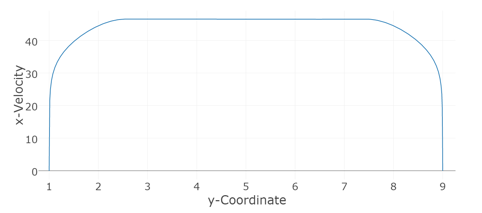
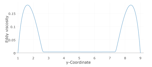
profile similar to the one used in an experimental study of the same problem. Figure 1 shows the profiles with
boundary layer definition for the second case.
The inlet velocity profile shows the presence of boundary layers at the edges while the
eddy viscosity profile shows a concentrated presence of eddy viscosity in the boundary
layer.
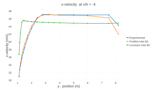
When comparing the results of the simulations run with the boundary conditions described
above you can see that the profiled inlet condition reflects the experimental data much more
accurately. The following plot compares the velocity profiles for both of the cases
mentioned above with experimental measurements at the location four times of step height
upstream of the step.Figure 3. Velocity Profiles at x/h=-4 for Profiled and Constant Inlet Boundary Conditions
Compared Against Experimental Data at the Same Location
You can see from the above comparison that using a boundary condition specification that
resembles the real physics is much more likely to provide a correct solution to the
problem.
The table below shows the difference between the reattachment length observed in the
backward facing step problem when a profile similar to the one in the experiment is provided
at the inlet, rather than using a constant value for the variables.
Table 1. Inlet Conditions Sensitivity for Backward Facing Step Simulation
Inlet condition type
Reattachment Length (m)
Constant
5.73
Velocity profile with boundary layer definition
5.96
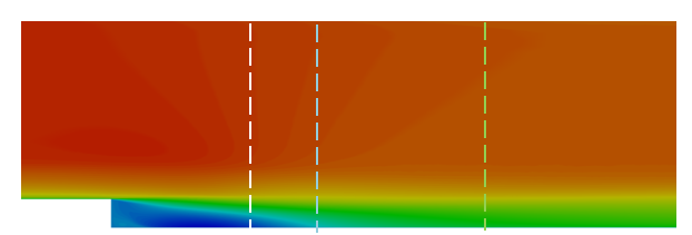
Presence of reverse flow at outlet conditions. Figure 4 shows three candidate locations
for an outlet boundary in the backward facing step model. The location represented by the
white line falls in a region of recirculating flow and would cause inaccurate results as
well as numerical difficulties due to the flow re-entering the domain. The location
represented by the blue line falls outside of the recirculation zone, but there is still a
significant amount of flow non-uniformity and falls fairly close to the recirculation
region. To minimize the impact of the outflow conditions on the solution it should be moved
further downstream, as shown by the green line.Figure 4. Candidate Locations for an Outlet Boundary on the Backward Facing Step
Model