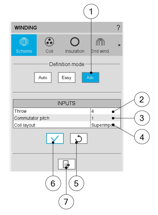
Advanced mode
User input parameters
| Label | Symbol | Value in easy mode |
| Throw | * | It is the coil pitch = number of slot pitches between coil input and coil output |
| Commutator pitch | Yc | Number of commutator segments between the segment connected to the coil input and the segment connected to the coil output. |
| Coil layout | * | Coil layout inside the slot –Superimposed or Adjacent |
Building the winding architecture – Advanced mode – Main principles
 |
|
| Building the winding architecture - Advanced mode | |
| 1 | Selection of the Advanced mode for building the winding architecture. |
| 2 |
Selection of the thrown (coil pitch) The proposed solutions depend on the number of slots and the number of poles. Throw <= ceil (number of slots / number of poles) |
| 3 |
Commutator pitch. Only the options compatible with a valid lap/wave winding are offered. |
| 4 |
Definition of the coil layout i.e. how the coil sections are distributed into the slot. The two possible choices are:
By default, the superimposed option is selected. |
| 5 | Icon to restore default input values. Default values are those which define the winding architecture by using the automatic mode. |
| 6 | Icon to apply inputs. Pressing the enter key twice applies inputs too. |
| 7 | Icon to export winding data into a text file |
 |
|
|
Graphical example of a winding defined with throw =5, commutator=-2, superimposed layout It corresponds to a lap, duplex, regressive winding. |
Winding Architecture – Outputs
Outputs are quite like 3-phase winding, but some specific parameters arise when dealing with DC machine winding. For shake of completeness the parameters are listed in the tables below.
Characterization - Winding
| Label | Symbol | Tooltip, note, formula |
| No. poles | p | Number of rotor pole pairs. 2p = number of poles. |
| No. slots | Nslots | Number of stator slots |
| No. Layers | Nlayers | Number of layers – For a DC winding it is always equal to 2 |
| Winding type | * | The winding type: Lap or wave |
| Plex | * | The plex (simplex, duplex or triplex) |
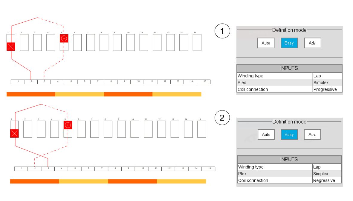
| Coil connection | * |
Connection type: Progressive or regressive Progressive connection: Commutator segments are connected following the same direction as winding (i.e., commutator pitch is positive). Regressive connection: Commutator segments are connecting following opposite direction as winding (i.e., commutator pitch is negative). |
| Commutator pitch | Yc | Number of commutator segments between the segment connected to the coil input and the segment connected to the coil output. |
| No. parallel paths | Ppaths |
Number of parallel paths. For a wave winding it is equal to twice the plex. For a lap winding it is equal to number of poles * plex |
| Coil layout | * | Coil layout inside the slot – Full, Superimposed or Adjacent. |
| Throw (coil pitch) | * | Number of slot pitch between coil input and coil output. |
Characterization - Coil
| Label | Symbol | Tooltip, note, formula |
| No. turns per coil | Turns | Number of turns per coil |
| No. turns in series | N_turns |
Number of turns in series N_turns=N_coils/(2×P_paths ) |
| No. conductors | N_cond |
Total number of conductors N_coils=2×N_slots×Turns |
Lengths
| Label | Symbol | Tooltip, note, formula |
| Total conductor length | * | Total conductor length. |
| Mean turn length | * |
Mean turn length. |
| Coil connection length | * |
Additional length corresponding to the connections between coils and commutator segments. |
| Axial overall length | * | Axial overall length. Length between the two extremities of the winding i.e. between connection side and opposite connection side. |