Fin
1. Overview
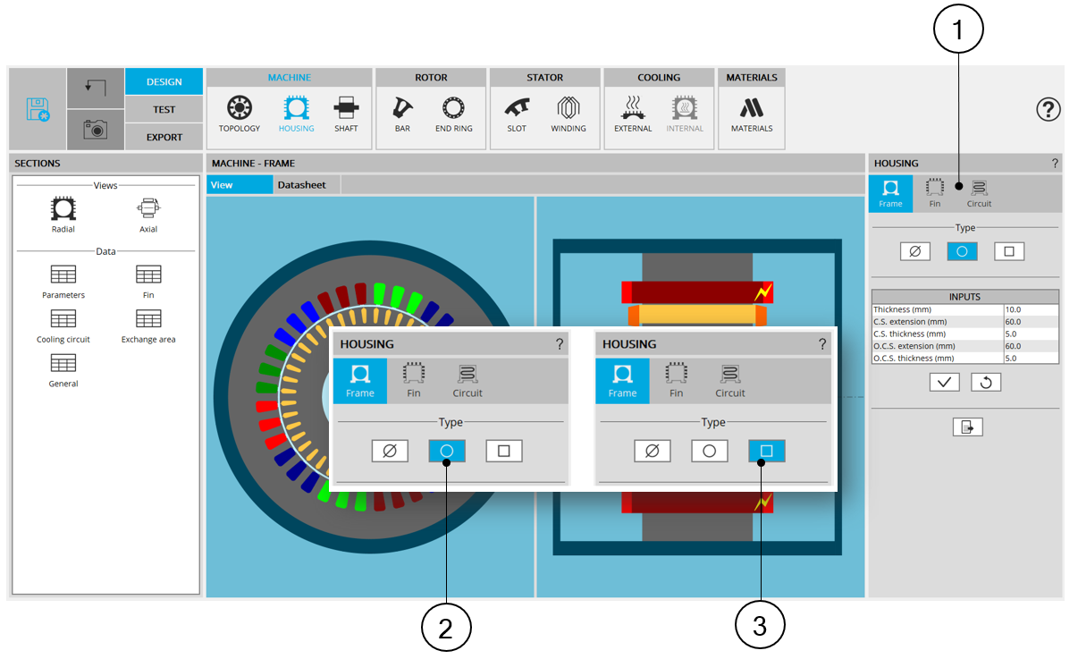
Access to the “Fin” area is unlocked when a frame is defined, whose shape is circular or square.
 |
|
| How to unlock the “Fin” area ? | |
| 1 | “Fin” area is unlocked (as well as the “Cooling circuit” area). |
| 2 | Selection of a circular shape frame. |
| 3 | Selection of a square shape frame. |
2. Type of fins
The tools available in the housing tab allow defining the fin topology.
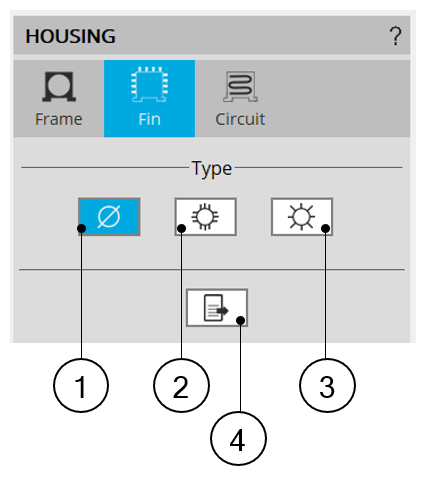
Three choices are available to define this topology: None, Parallel or Radial.
By default, fin type is set to “None”. There is no fin.
 |
1 |
Default setting : Fin type is « None » The housing has no fin. |
| 2 | Button to select parallel type fins. | |
| 3 | Button to select radial type fins. | |
| 4 | Icon to export fin data into *.txt or *.xls files. | |
| Fin type available | ||
3. Parallel type fins – Topologies and dimensions
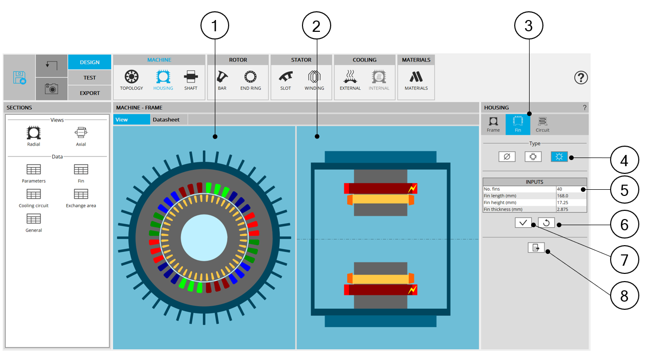
3.1 Parallel type fin area
 |
|
| Parallel type fin design area | |
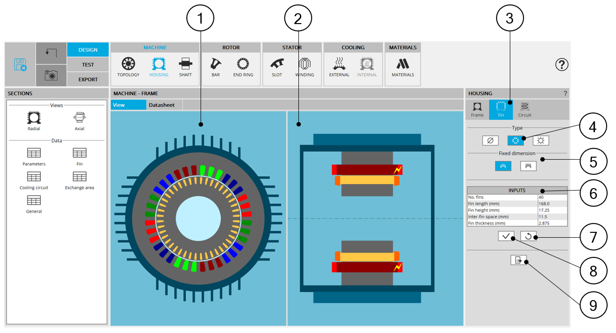
| 1 | Radial view of the motor, including the housing topology with fin topology and dimensions. |
| 2 | Axial view of the motor, including the housing topology with fin topology and dimensions. |
| 3 | The section fin is selected to define the type and dimensions of the fins. |
| 4 | Selected button to define parallel type fins. |
| 5 | Two ways are possible to define the fin dimensions: "Height" and "Extension" options. See below illustrations. |
| 6 | User input parameters to define the fin dimensions. For more information see below. |
| 7 | Button to restore default input values. |
| 8 | Button to apply inputs. Pressing the enter key twice applies inputs too. |
| 9 | Icon to export frame data into *.txt or *.xls files. |
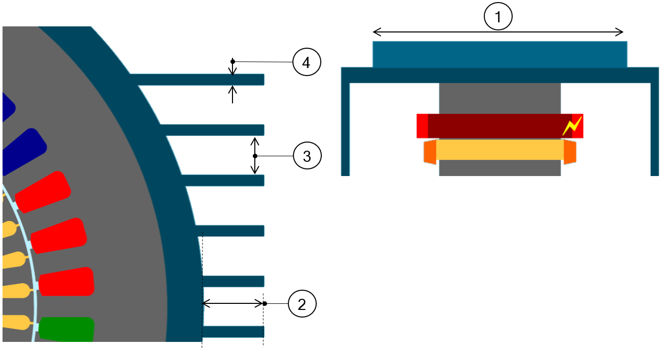
3.2 Parallel type fins with constant height – Inputs
 |
|
| Parallel type fin with constant height - Inputs | |
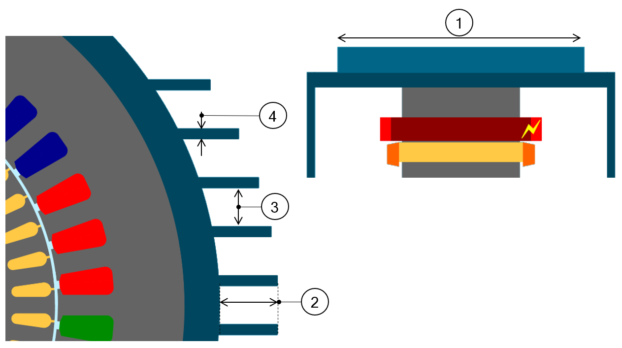
| # | No. fins (Number of fins) which spread all around the housing – Minimum allowed value = 12. |
| 1 | Fin length |
| 2 | Fin height |
| 3 | Inter-fin space |
| 4 | Fin thickness |
3.3 Parallel type fins with constant total extension – Inputs
 |
|
| Parallel type fin with constant total extension - Inputs | |
| # | No. fins (Number of fins) which spread all around the housing – Minimum allowed value = 12. |
| 1 | Fin length |
| 2 | Fin extension |
| 3 | Inter-fin space |
| 4 | Fin thickness |
4. Radial type fins – Topologies and dimensions
4.1 Radial type fin area
 |
|
| Radial type fin design area | |
| 1 | Radial view of the motor, including the housing topology with fin topology and dimensions. |
| 2 | Axial view of the motor, including the housing topology with fin topology and dimensions. |
| 3 | The section fin is selected to define the type and dimensions of the fins. |
| 4 | Selected button to define radial type fins. |
| 5 | User input parameters to define the fin characteristics. For more information see below. |
| 6 | Button to restore default input values. |
| 7 | Button to apply inputs. Pressing the enter key twice applies inputs too. |
| 8 | Icon to export frame data into *.txt or *.xls files. |
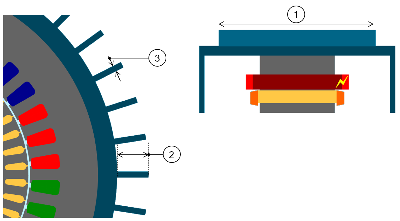
4.2 Radial type fins – Inputs
 |
|
| Parallel type fin with constant height - Inputs | |
| # | No. fins (Number of fins) which spread all around the housing – Minimum allowed value = 12. |
| 1 | Fin length |
| 2 | Fin height |
| 3 | Fin thickness |