Frame
Housing - Frame
 |
|
| Circular shape frame design area | |
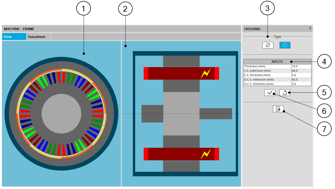
| 1 | Radial view of the motor, including the housing topology and dimensions. |
| 2 | Axial view of the motor, including the housing topology and dimensions. |
| 3 | Selected button to consider a frame or not. |
| 4 | User input parameters to define the frame dimensions. For more information see below. |
| 5 | Button to restore default input values. |
| 6 | Button to apply inputs. Pressing the enter key twice applies inputs too. |
| 7 | Icon to export frame data into *.txt or *.xls files. |
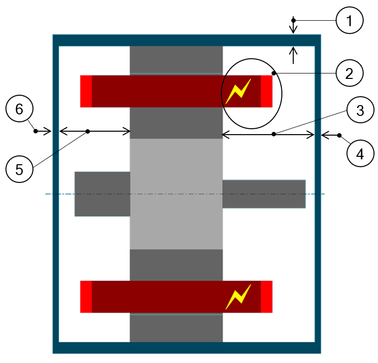 |
1 |
Thickness of the frame. Allowed range of values ]0, 50] mm. |
| 2 | Connection side (C.S.) is identified by yellow lightning. | |
| 3 |
Connection side extension. Allowed range of values [0, 20000] mm. |
|
| 4 |
Connection side – End-plate thickness. Allowed range of values ]0, 50] mm. |
|
| 5 |
Opposite connection side extension. Allowed range of values [0, 20000] mm. |
|
| 6 |
Opposite connection side – End-plate thickness. Allowed range of values ]0, 50] mm. |
|
| User input parameters to define frame dimensions in the axial view | ||