SHAFT
Shaft - Overview
 |
|
| SHAFT design area | |
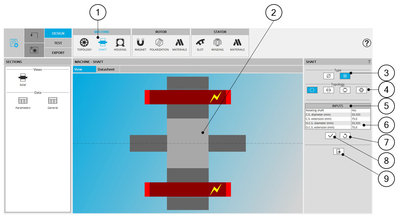
| 1 | Selection of the MACHINE subset: SHAFT panel (Click on the icon SHAFT) |
| 2 | Visualization of the motor axial view to visualize the shaft topology and dimensions. |
| 3 |
Choice of the shaft type. Two types are available:
If shaft type is solid, Topology and dimensions of end-shaft must be defined. Note: Connection side (C.S.) is identified by yellow
lightning.
Note: Range of definition for dimensions: [0, 20000]
mm.
|
| 4 | Topology of the shaft must be defined: Solid, Solid with hollow, Solid with ring, Solid with hollow and ring |
| 5 | Shaft input data to be defined |
| 6 |
If shaft type is solid, end-shaft must be defined. First indicate if the shaft is rotating or not Note: Connection side (C.S.) is identified by yellow
lightning.
Note: Range of definition for dimensions: [0, 20000]
mm.
|
| 7 | Button to restore default input values. |
| 8 | Button to Apply inputs. Pressing the enter key twice applies inputs too. |
| 9 | Icon to export shaft data into *.txt or *.xls files. |