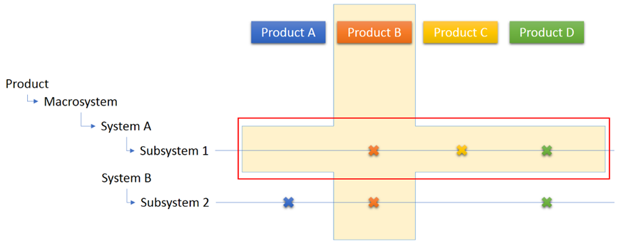
A BoM is a hierarchical structure, commonly not balanced, describing a complex product.
A BoM that is created using the Functional View (the granular view of a product) is called a
Functional BoM.
Select Snapshots
You must first select a Snapshot before you create or edit a Concept.
To select a Snapshot:
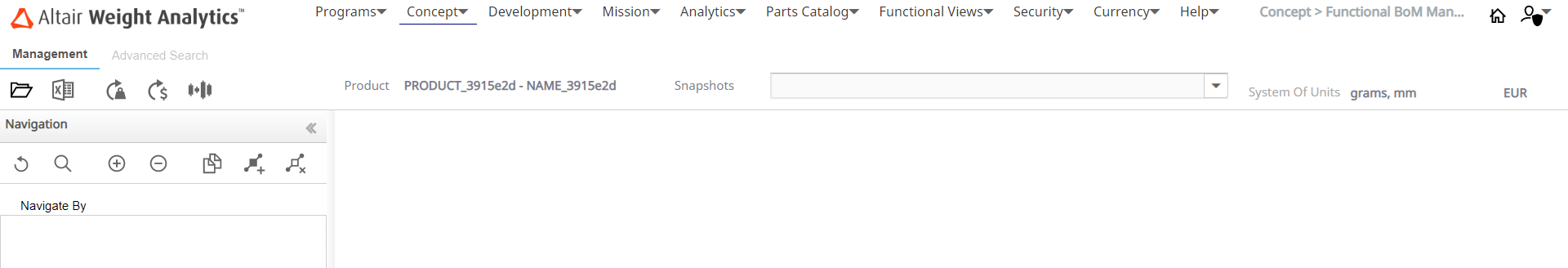
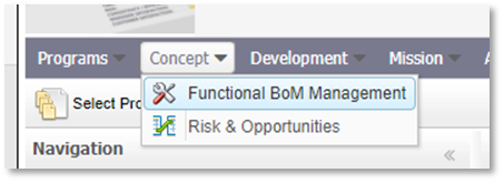
Click Concept → F-BoM Management.
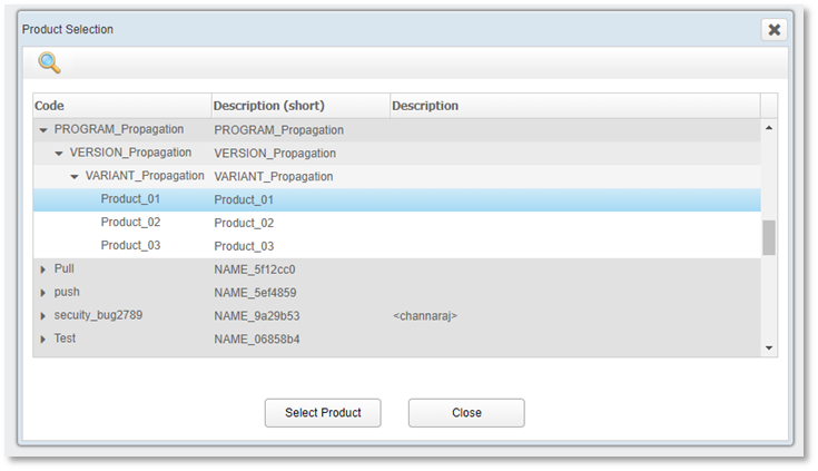
Click Select Product.
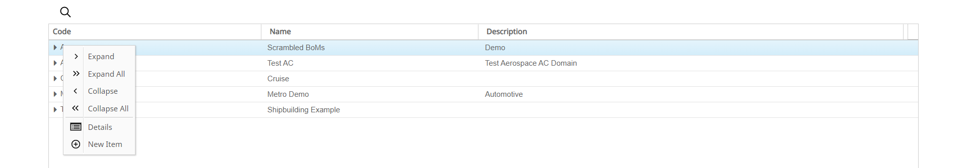
From the Program tree of the Product Selection dialog box, select the Product which has Concepts
defined.
The Product is selected and the Concepts defined for the selected
Product are displayed in the Snapshots dropdown list.
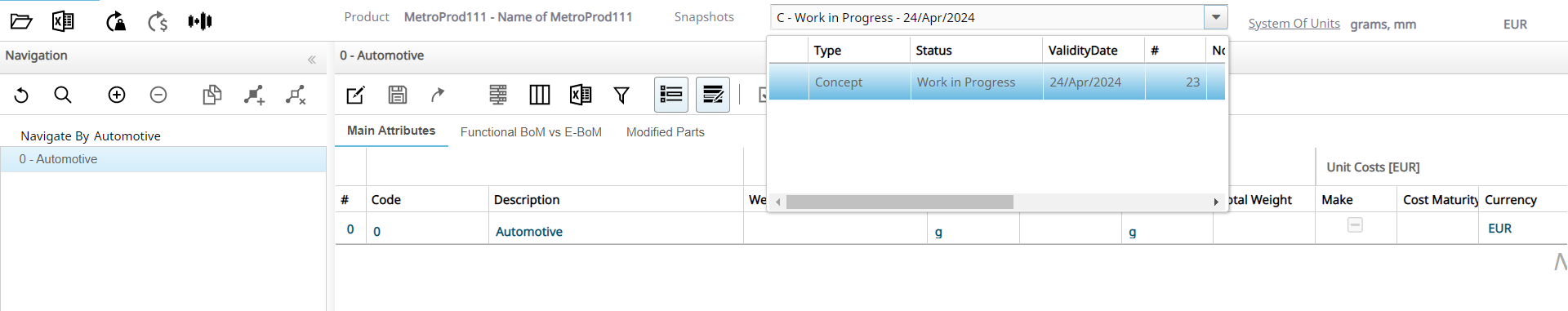
Click the required Concept from the dropdown list.
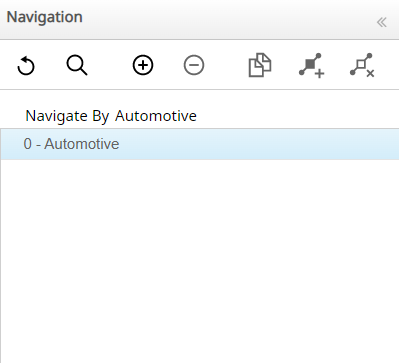
The Functional View associated with the Concept is displayed in the
Navigation panel.
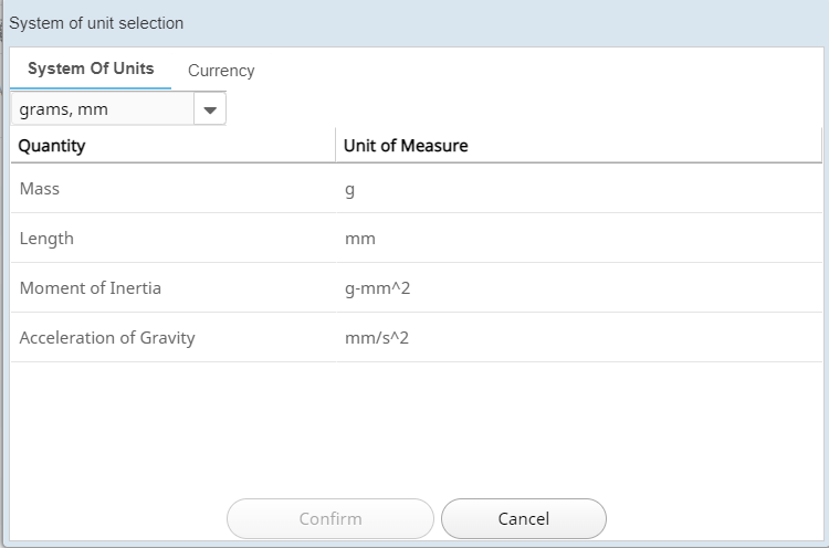
Click System Of Units to change the system of units.
The System of unit selection dialog box is displayed.
Select the required System of units from the dropdown list and click Confirm.
The unit selection will be accepted and applied to the Concept.
Add Systems and Sub-systems
You can add two levels of functional hierarchy to a Concept also called Nodes. The
top-level node is assigned a code of 0. Systems defined under the top-level
node are assigned the codes of 01, 02,
03, and so on.
To add systems and sub-systems:
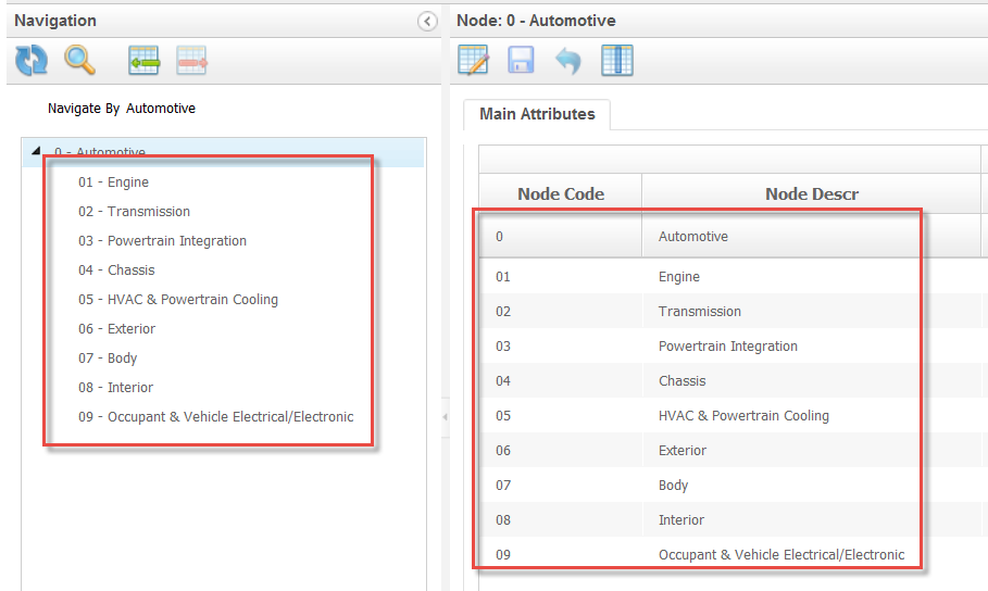
In the Navigation panel, click the top-level node in the Functional
View.
Click Add Item.
The Select Node dialog box is displayed.
Select the check boxes for the nodes/systems that you want to add to the
view.
To add all the child nodes of the selected systems, select the Add all Children for Selected Item check box.
Click Add Selection.
The selected nodes/systems will be added to the Navigation area and in the Main Attributes tab.
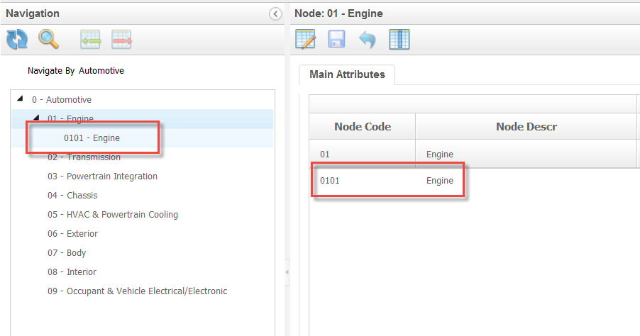
Add a Sub-System
Select the system to which you want to add a sub-system.
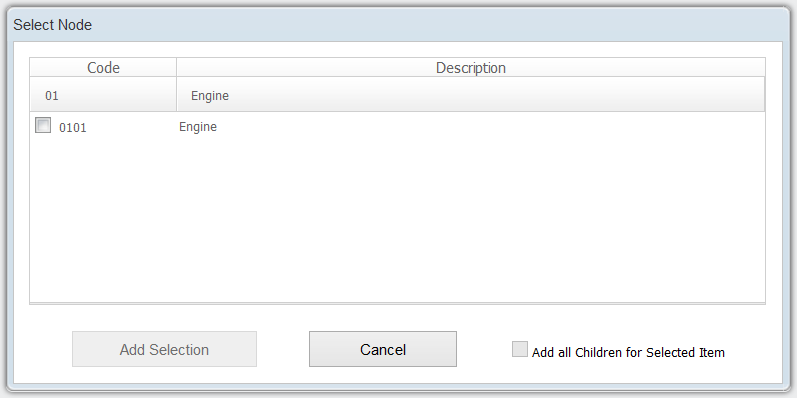
Click Add Item.
The Select Node dialog box is displayed.
The dialog box displays all the sub systems that can be added to the
selected system.
Select the check box next to the sub-systems that you want to add and click
Add Selection.
The selected nodes/sub-systems will be added to the Navigation panel and in the Main Attributes tab.
Similar to the parent systems, you can modify the attributes of the
sub-systems by clicking the Enable Changes icon.
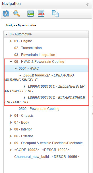
Add Existing or Carry Over Parts/Systems/Assemblies
After you reach the leaf level of the Functional View, WA allows you to add real P/Ns of carry over parts or new parts, so that the Functional BoM
starts to transform into a real Engineering BoM.
To add existing or carry over parts:
Select the last level of the Functional View.
Click Add Part.
Two tabs are displayed, one for the Existing Part
and the other for the New Part.
Select the existing part and then add the available parts.
Note: The user can not only add single parts, but also
assemblies.
Delete a System/Sub-system/Part
WA allows you to delete a system, sub-system, or part
from a Concept.
To delete a system, sub-system, or part:
Click the entity that you want to delete from the Navigation panel.
Click Remove Item.
A confirmation dialog box is displayed.
Click OK.
The entity will be deleted from the Concept and the
database.
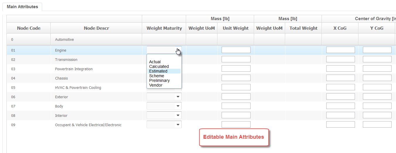
Edit Concept or System Main Attributes
WA allows you to edit and modify the Main Attributes of
the Systems added to the Concept.
To edit concept or system Main Attributes:
Click Enable Changes.
The columns in the table that can be edited will become editable.
Modify the required changes to the columns in the table.
Click the Save Changes icon.
The changes made will be updated in the database.
Note: In case you have defined one or more Reporting
Functional Views at the Program level that are different from the Management
Functional View in the Concept phase, you can see additional editable
columns corresponding to those Functional Views for each
node.
Set Targets for Each System or Sub-system
WA allows you to set targets for each system or
subsystem.
To set targets for each system or subsystem:
Enter the values in the Target Weight column of each
sub-system.
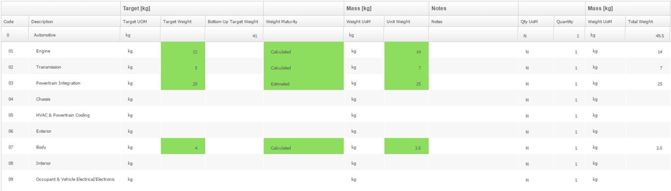
Click Save and then click
Recalculate.
The Bottom Up Target Weight value is
displayed.
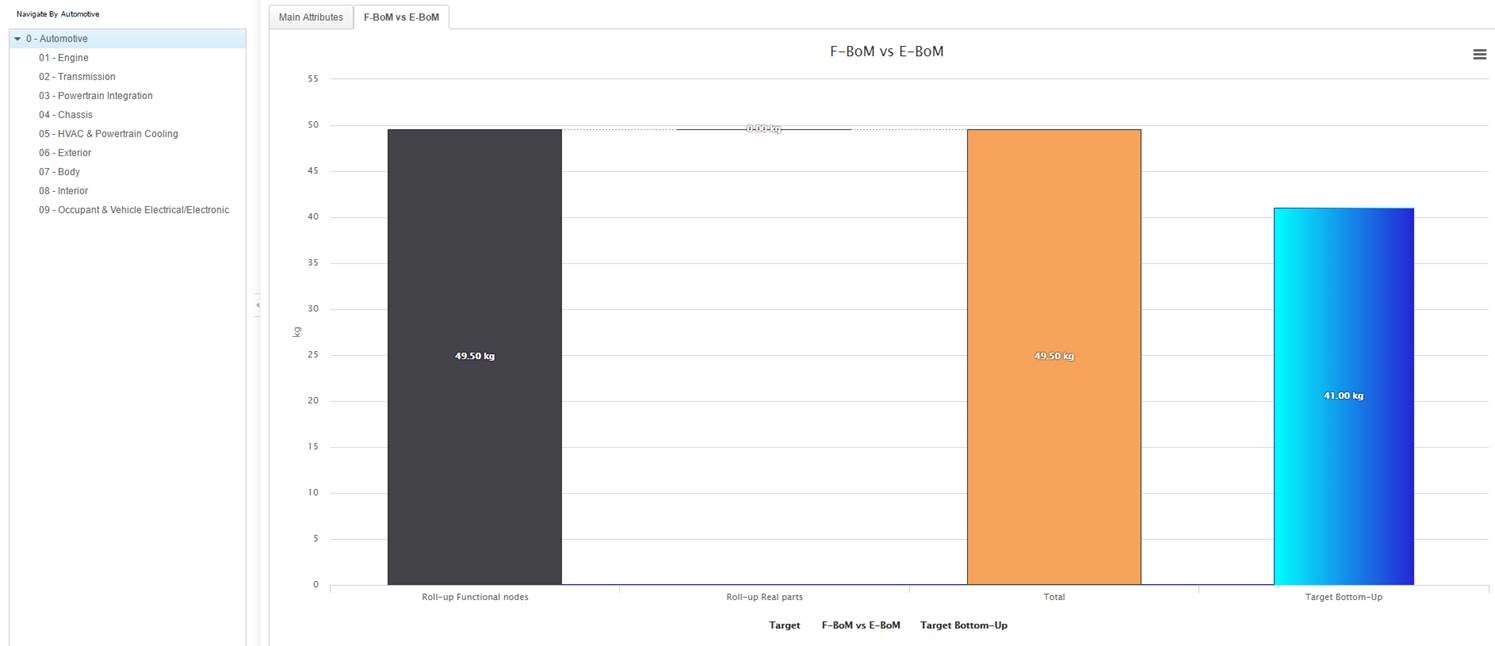
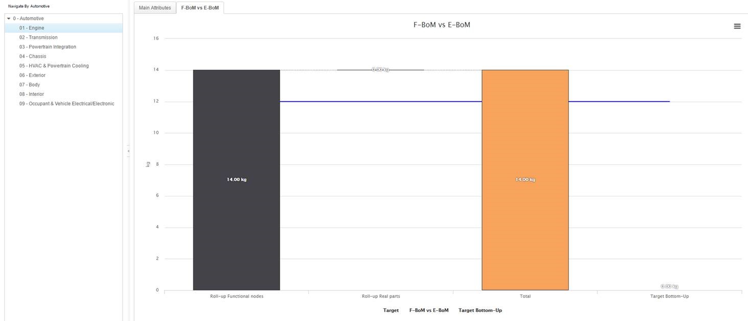
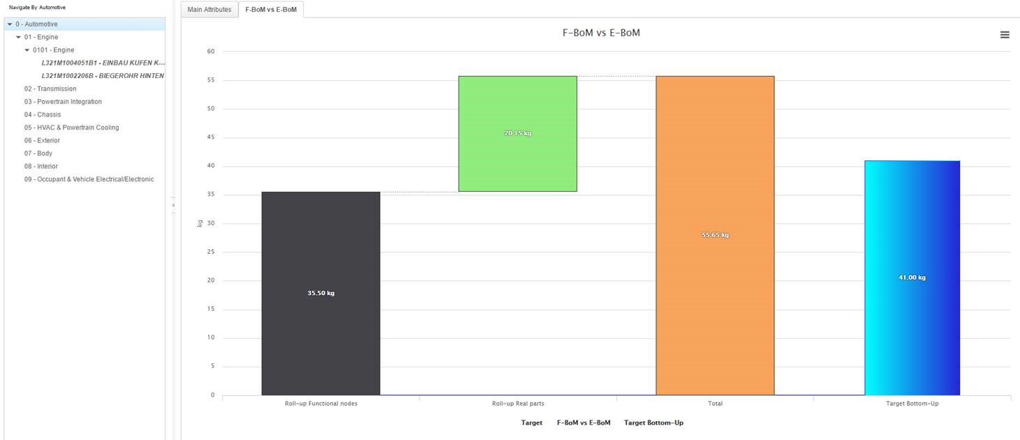
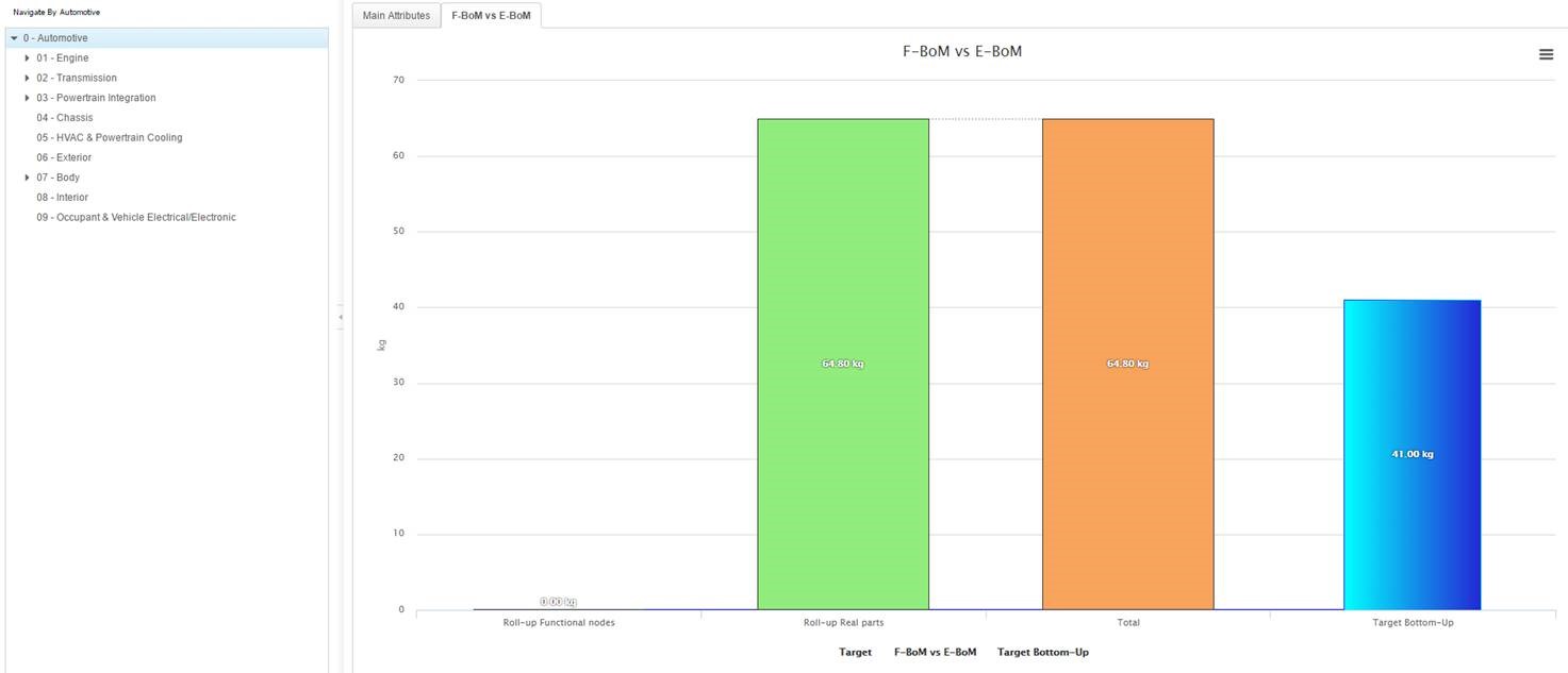
F-BoM vs E-BoM Comparison
Using this panel, you can compare the portion of the weight which is assigned to the
real parts/assemblies to the portion of the weight assigned to the functional
tree.
To compare F-BoM and E-BoM:
The available cases in this comparison are:
100% of the weight assigned to functional groups.
Product Root is selected
Drill down into functional breakdown (Engine group)
x% of W from Functional groups, y% of W from real parts
100% of Product Weight coming from real parts
After any change in Weight/Maturity recalculation button needs to be
used in order to get bar charts updated.
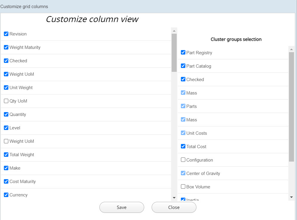
Customize Grid Columns
You can customize the grid columns by adding selected columns to the table and
removing the unselected columns from the table.
To customize the column view:
Click the
icon to customize the columns view.
In the Customize grid columns dialog box, select the
column or cluster checkboxes that you want to include in the table.
The list of check boxes on the left are the individual columns that can be
added or removed from the table. The check boxes in the Cluster groups selection selection list are the categories of columns. If you select any cluster from
this list, all columns that belong to this cluster are selected automatically.
Click Save and Close to save the
changes that you have made.
The selected columns will be added to the table and the unselected
columns will be removed from the table.
Share System and Sub-ssystem
You can apply the changes made to a selected Product (in a specific Program) to all the
other Products belonging to the same Program.
The following features are available:
Share Node
Where Used
Set as Specific
Copy Node
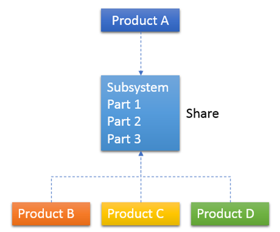
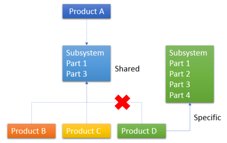
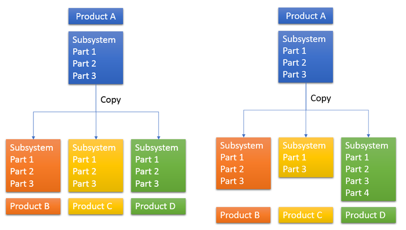
Share Node
The Share feature allows to share among multiple products a selected node.
Only leaf nodes in Functional breakdown structure can be shared. When a node is shared,
any change made in one product (add/remove part, Mass setting) is propagated in all the
products in which it is shared.
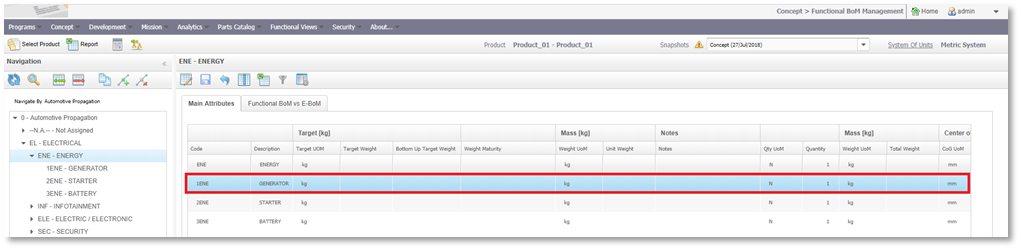
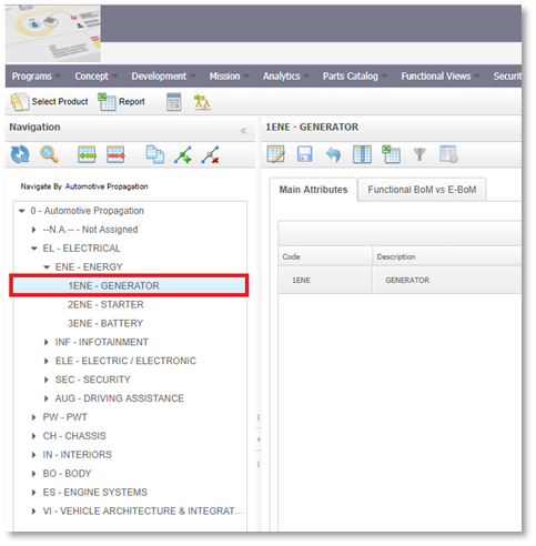
To share a node:
Click on Concept\Functional BoM Management menu
item.
Select a product.
Select the node that must be shared from the Structure tree (on the left
side).
Note: This must be a leaf node.
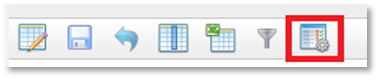
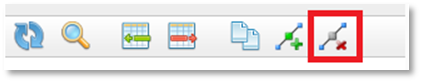
Click on Copy to/Share button in the toolbar above the
navigation tree.
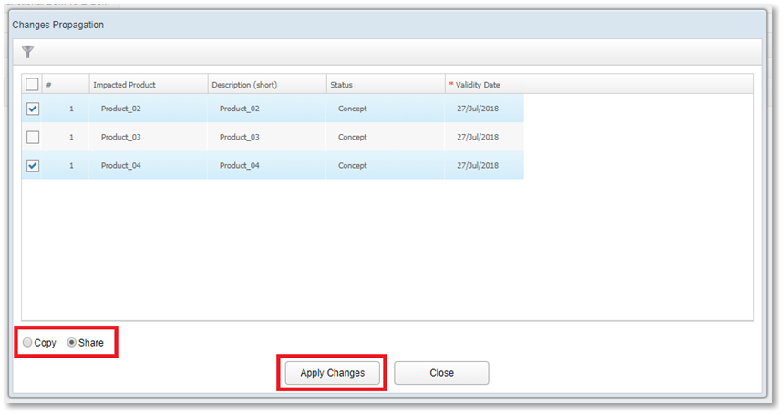
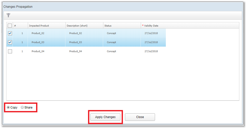
A pop-up window containing all the other Program’s Products will be
displayed.
Select the Products that will share the selected node.
Select the Share option.
Click on Apply Changes button.
The node will be shared between all the selected products. All changes
made in one of the product sharing the same node, will be propagated in the
other ones.
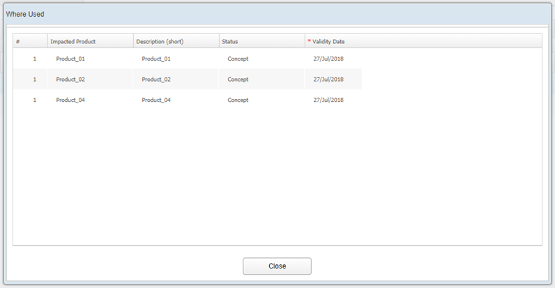
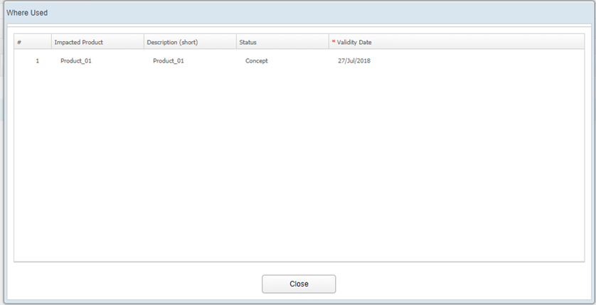
Where Used
The Where Used feature allows you to know if a node is shared and the products with
which it is shared.
To access Where Used:
Select the node in the grid of the working area.
Click Where Used above the grid.
A pop-up window displays the products that share the node.
In case of a node that is not shared, the pop-up will display only the
product that you are currently working with.
Set as Specific
A shared node can be removed from sharing and set as specific. The changes made in a
node that is set as specific are not propagated to the other products.
To set a node as specific:
Select a Product sharing a node.
Select the shared node on the navigation tree.
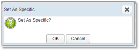
Click on Set as Specific button in the toolbar above the
navigation tree.
Click Ok on confirmation message box.
The node will not be shared any more. The changes made in one product will
not be propagated in the other ones.
Copy Node
This feature allows to make a copy of a selected node (with all its own parts) in one
or more Products. Only leaf nodes in functional breakdown structure can be copied.
In this case changes made in one product (Add/Remove part, Mass setting) will not be
propagated to other Products.
Follow the below steps to copy a node:
Click on Concept\Functional BoM Management menu
item.
Select a Product.
Select the node that must be copied from the Structure tree (on the left side).
Note: This must be a leaf node.
Click on Copy to/Share button in the toolbar above the
navigation tree.
A pop-up window containing all the other Program’s Products will be
displayed.
Choose the Products to which the selected node to be copied.
Select the Copy option.
Click on Apply Changes button.
The node will be copied in all the selected products. The changes made
in one product will not be propagated in the other ones.
Extract E-BoM from F-BoM
You can create a new Product in the E-BoM by extracting the E-BoM from the F-BoM.
To extract E-BoM from F-BoM:
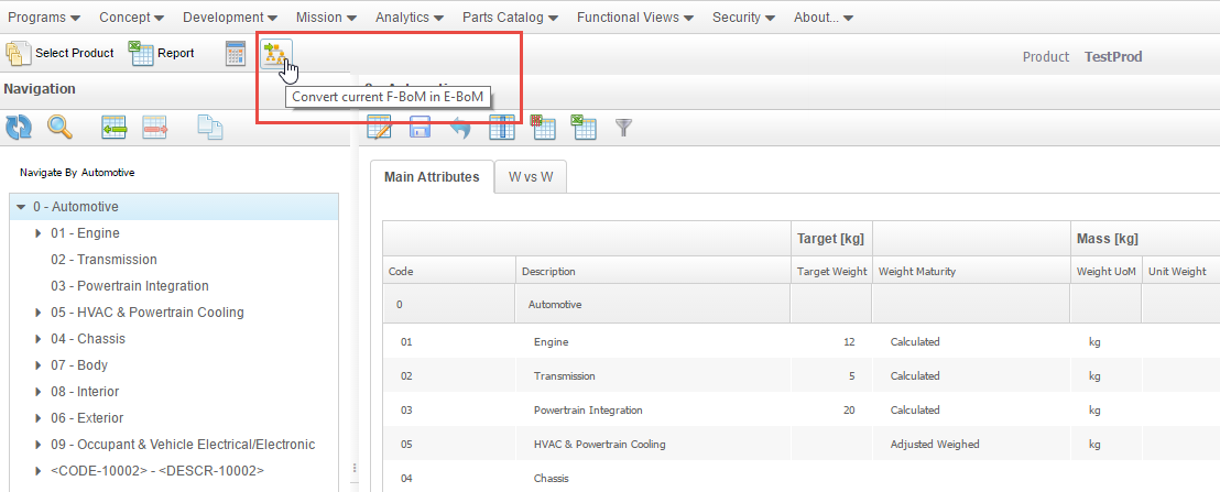
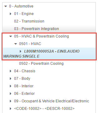
Navigate to Concept → F-BoM Management.
Select any node of the functional breakdown (left hand side).
Click Convert current F BoM in E-BoM button.
The Choose The Export Method window is
displayed.
Click Next button.
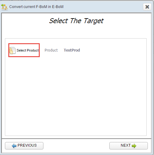
The Select The Target window is
displayed.
Select the target using the Select Product option.
Click Next button
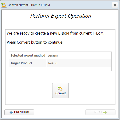
The Perform Export Operation window is
displayed.
Click Convert button.
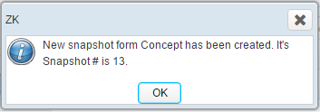
A snapshot creation successful message is displayed.
Click OK button in the message window.
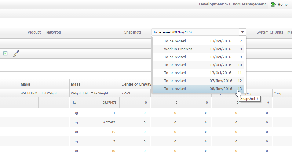
Navigate to Development → E-BoM Management.
Select the Snapshot 13 from the
Snapshots drop down list.
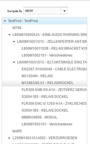
Switch to E-BoM view using Navigate By drop down.
The real assemblies and/or parts are displayed.
Note: The functional view is carried over to E-BoM only when the functional
views of source in concept snapshot and the target product are
same.
Cost Attributes
WA allows you to define cost attributes for a Product
using F-BoM Management.
To define cost attributes:
Warning: This
functionality is not fully supported in version 2023.1 in F-BoM
Management.
Click Concept → F-BoM Management.
Select a Product belonging to a Program associated with a Functional View and
having a Concept Snapshot.
Check the column visibility by clicking the Customize grid
columns icon.
The following groups are displayed: Target Costs,
Unit Costs, and Total
Cost.
Select a Functional Node (at any hierarchical level) for which you want to view
or edit the cost attributes.
The Target Costs and the Unit Costs sections display the respective cost
attributes.
In the Target Costs section, specify the following
attributes:
Currency
Target Cost
Select an assembly or part for which you want to view or edit the cost
attributes.
You can specify the cost attributes as shown in the following example where
the cost attributes list is displayed. The effective list depends on your
WA configuration.
Make: Flag that indicates if the part or assembly is a
Make or Buy part.
Cost Maturity: Indicates the maturity to be selected from a list
(configurable for your requirements).
Actual
Adjusted Calculated
Calculated
AI Estimated
Estimated
Currency: Indicates the currency to be selected from a list of multiple
currencies
Raw Material: Cost Element
Transport: Cost Element
Standard Extra: Cost Element
Amortization Quota: Cost Element
Rejected Materials: Cost Element
Value Added: Cost Element
Material Cost: Cost Element
Manpower: Cost Element
Total Cost: Indicates automatic calculation by WA and is a non-editable field.
Total Currency: Indicates the currency of the total cost.
Cost Impacts: Flag that is automatically computed by WA indicating if the related part will
contribute to the Vertical roll-up.
Cost Notes: Indicates any additional notes.
To edit the cost attributes, click the Enable Changes icon.
If you enter a cost value on a row, you must ensure that you indicate both
Maturity and Currency in the same row.
Click the Save Changes icon to save the changes made to the attributes.
WA automatically calculates the Horizontal
roll-up while saving changes and populates (when possible and compliant with
Maturity rules) the Total Cost value in each modified row.
Note: A triangular warning icon appears next to the
Snapshot name.
The red icon
indicates both weight and cost roll-up operations.
The yellow icon
indicates weight roll-up operations only.
The green icon indicates
cost roll-up operations only.
Click the icon to recalculate the cost roll-up.
WA calculates Vertical Roll-up summing from
leaves to root of the Functional View each Cost Attribute and Total Cost
following general rules related to Maturity of Cost values.
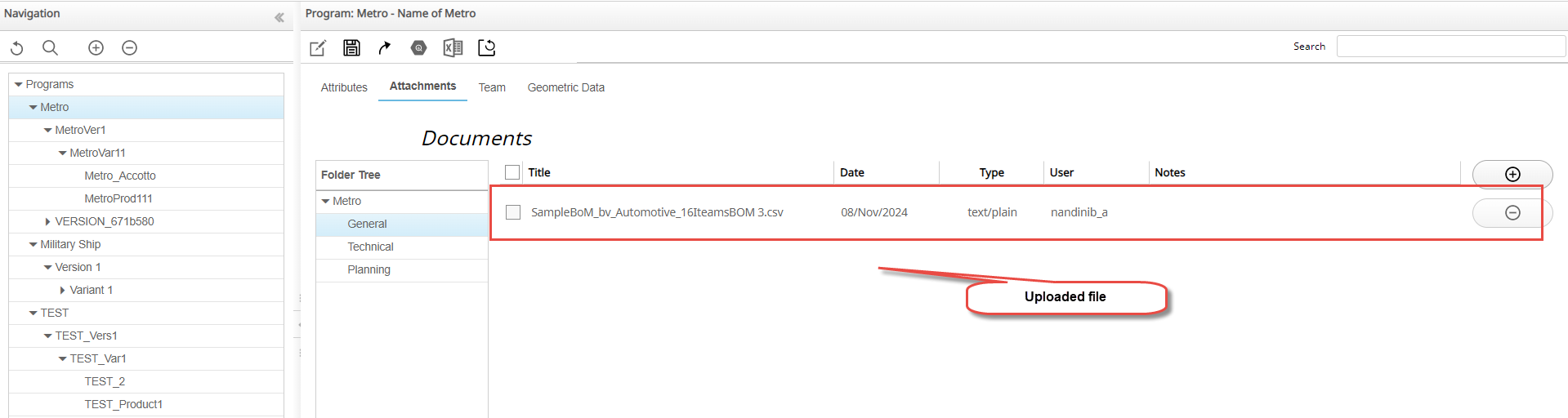
Add Attachments
WA allows you to add external documents at the Program,
Version, Variant, and Product levels. You can upload and group the files under three
pre-defined categories such as General, Technical, and Planning. You can also upload files
at the top level outside of these three categories.
To add attachments:
Select the Attachments tab.
Select the required category from the Folder Tree.
Click the
icon and then click the icon to add an attachment .
Navigate to the file that you want to upload and click Open.
The file will be selected and listed in the Documents table.
Click the Save Changes icon.
After completing the upload and deletion of files, you must save the changes
made to the Attachments tab.
Note:WA does not allow you to attach executable files
for security reasons and performs two types of checks - one for file
extensions, and second for file content.
Delete Attachment
To delete attachments:
Select a check box in the first column of the Documents table.
Click the Delete Fileicon.
The selected file is deleted from WA
and the Documents table.
 .
The Select Node dialog box is displayed.
.
The Select Node dialog box is displayed.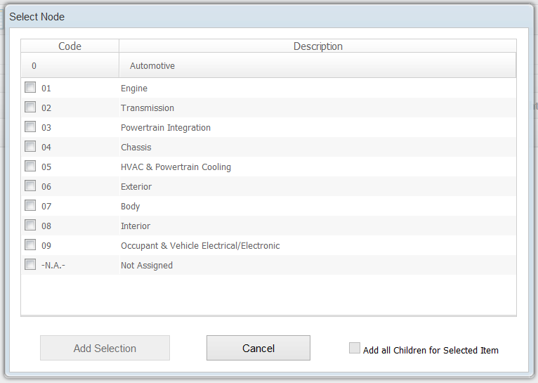
 icon.
icon. 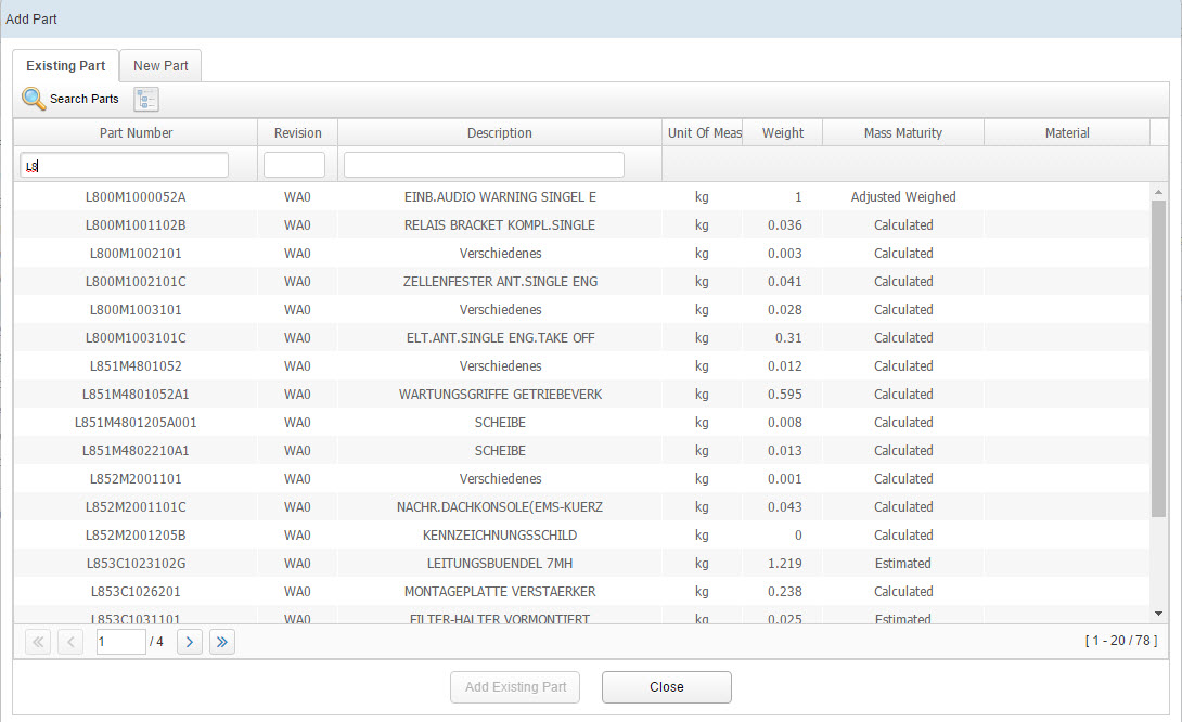
 .
A confirmation dialog box is displayed.
.
A confirmation dialog box is displayed.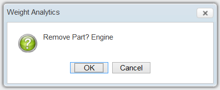
 icon.
The changes made will be updated in the database.Note: In case you have defined one or more Reporting Functional Views at the Program level that are different from the Management Functional View in the Concept phase, you can see additional editable columns corresponding to those Functional Views for each node.
icon.
The changes made will be updated in the database.Note: In case you have defined one or more Reporting Functional Views at the Program level that are different from the Management Functional View in the Concept phase, you can see additional editable columns corresponding to those Functional Views for each node.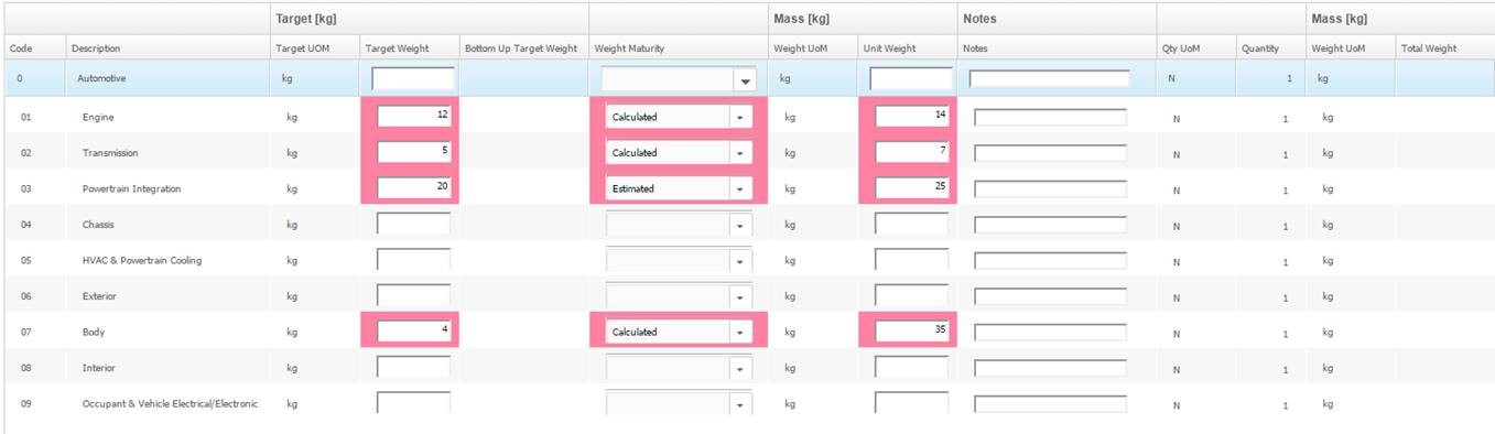
 icon to customize the columns view.


 Note: The functional view is carried over to E-BoM only when the functional views of source in concept snapshot and the target product are same.
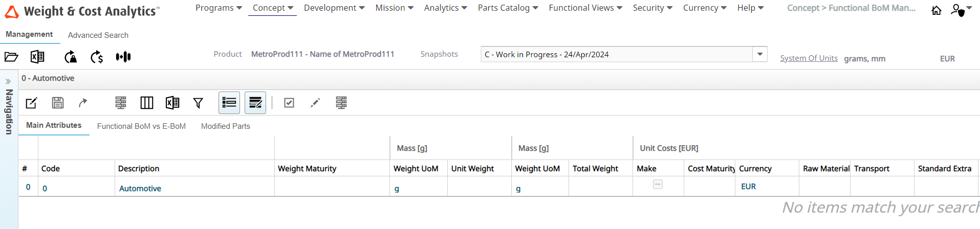
 icon.
If you enter a cost value on a row, you must ensure that you indicate both Maturity and Currency in the same row.
icon.
If you enter a cost value on a row, you must ensure that you indicate both Maturity and Currency in the same row. icon to save the changes made to the attributes.
WA automatically calculates the Horizontal roll-up while saving changes and populates (when possible and compliant with Maturity rules) the Total Cost value in each modified row.Note: A triangular warning icon appears next to the Snapshot name.
icon to save the changes made to the attributes.
WA automatically calculates the Horizontal roll-up while saving changes and populates (when possible and compliant with Maturity rules) the Total Cost value in each modified row.Note: A triangular warning icon appears next to the Snapshot name. icon
indicates both weight and cost roll-up operations.
icon
indicates both weight and cost roll-up operations. icon
indicates weight roll-up operations only.
icon
indicates weight roll-up operations only. icon indicates
cost roll-up operations only.
icon indicates
cost roll-up operations only. icon to recalculate the cost roll-up.
WA calculates Vertical Roll-up summing from leaves to root of the Functional View each Cost Attribute and Total Cost following general rules related to Maturity of Cost values.
icon to recalculate the cost roll-up.
WA calculates Vertical Roll-up summing from leaves to root of the Functional View each Cost Attribute and Total Cost following general rules related to Maturity of Cost values.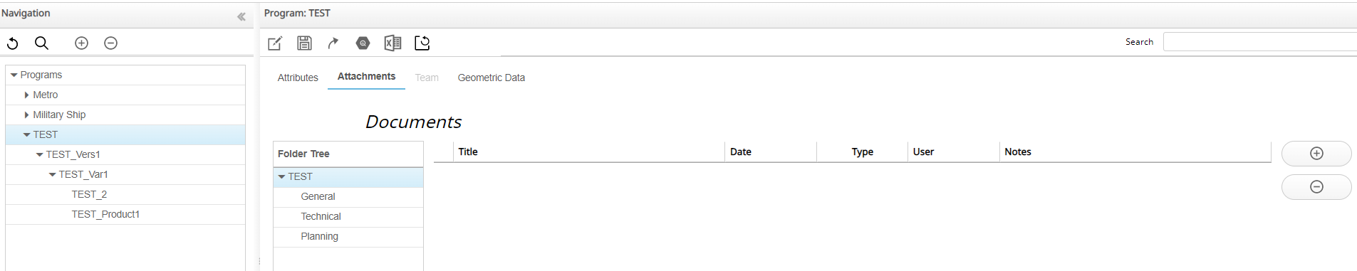
 icon to add an attachment .
 icon.
The selected file is deleted from WA and the Documents table.
icon.
The selected file is deleted from WA and the Documents table.