PDN Impedance
This item checks whether the PDN Impedance of the specified Power pins are higher than the target impedance specified.
In PCB, the power line generally refers to a power network that connects the power source(VRM) and the load components. The characteristics of these power trace configurations can be determined by the power delivery network (PDN) of the PCB. PDN operates like a passive component such as a coil or capacitor, depending on its physical properties. Resonance occurs due to these passive components, and the current flowing through the resonance structure causes signal distortion and EMI problems. Therefore, precise analysis of PDN Impedance is very important in the design phase.
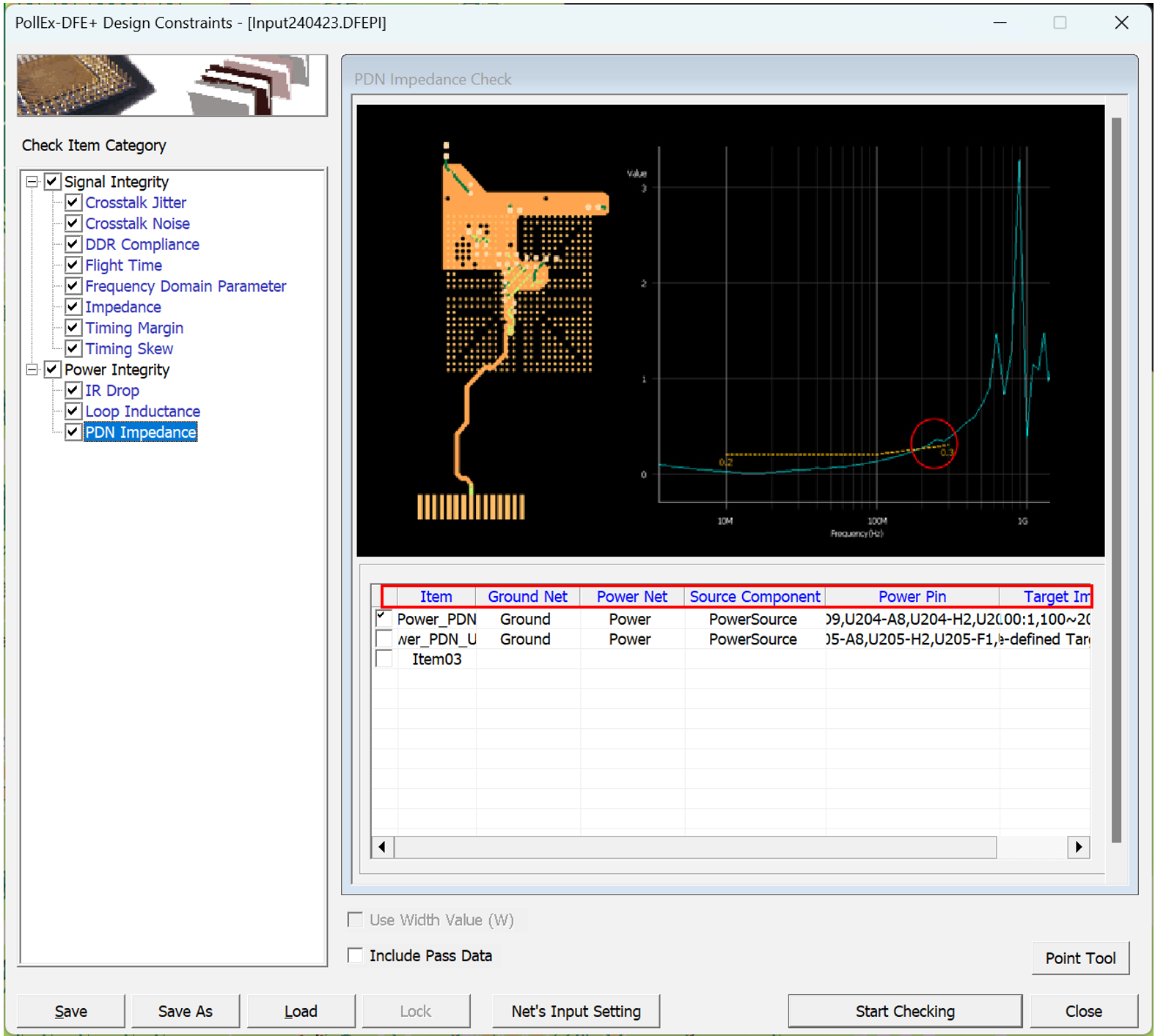
- Item: Sub item name. User can enter arbitrary name.
- Ground Net: Select target ground net groups to be tested. Allow multiple net groups.
- Power Net: Select target power net groups to be tested. Allow multiple net groups.
- Source Component: Select component groups that supply power.
- Power Pin: Upon clicking this field, the Selected Power Net Pins dialog will
be open. You can set the required power source pins and load pins for each
power net.
- Use auto setting: When this option is selected, among all the pins connected to each power net, the pins connected to the source component are automatically selected as source pins, and the remaining pins are automatically selected as load pins. The setting contents cannot be changed.
- Use user defined setting: Selecting this option allows the user to arbitrarily select power source pins and power load pins.
- Target Impedance: Upon clicking this field, the Target Impedance dialog
opens. You can set allowable target impedance value for each frequency
band.
- Use pre-defined Target Impedance: Upon selecting this option, DFE will use the Target Impedance value preset in the component.
- Use user defined Target Impedance: Upon selecting this option, you
can arbitrary set allowable Target Impedance value. There are three types way to set up the target impedance: Linear, RLC and RL.
- Linear: Setup target frequency (Min and Max) and target
impedance value(ohm) directly.
Figure 2. 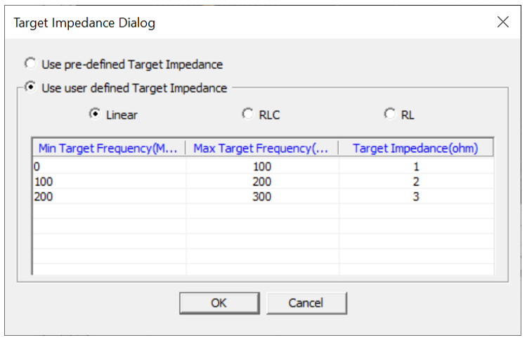
- RLC: Set up the target impedance by entering
Capacitance(pF), Resistance(ohm) and Inductance(nH)
value.
Figure 3. 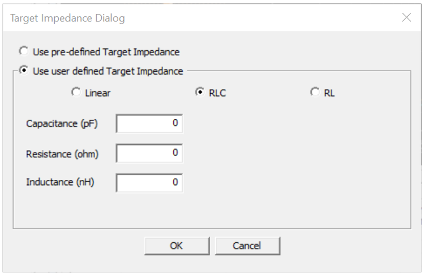
- RL: Set up the target impedance by entering
Resistance(ohm) and Inductance(nH) value.
Figure 4. 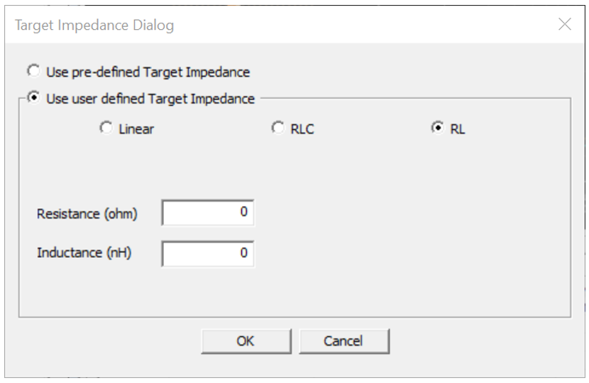
- Linear: Setup target frequency (Min and Max) and target
impedance value(ohm) directly.