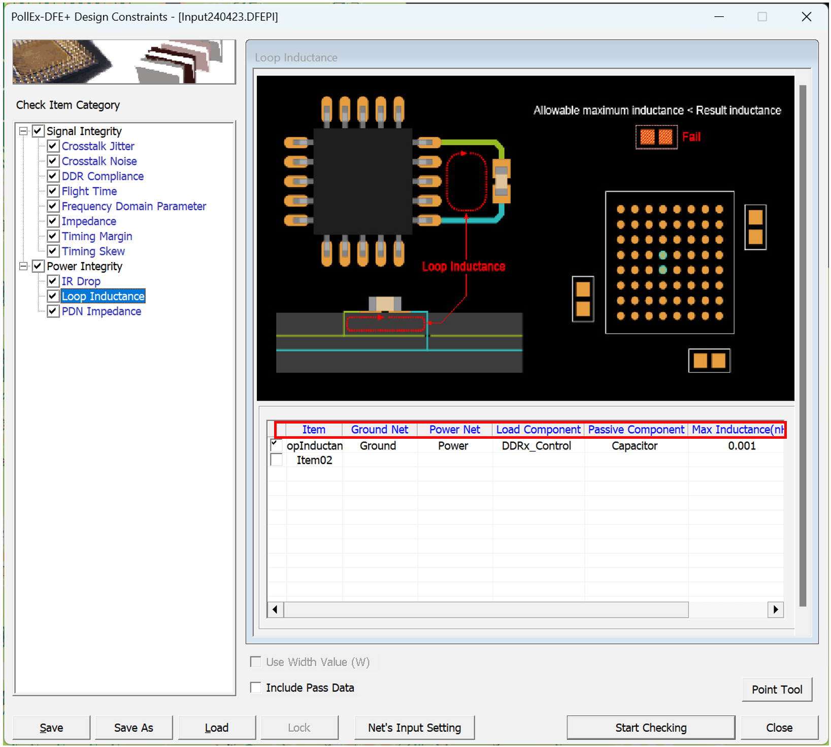
Loop Inductance
This item checks whether the loop inductance between the power pin and the decoupling capacitor exceeds the specified value.
In PCB, the power line generally refers to a power network that connects the power source(VRM) and the load components. The characteristics of these power trace configurations can be determined by the power delivery network (PDN) of the PCB. PDN operates like a passive component such as a coil or capacitor, depending on its physical properties. Resonance occurs due to these passive components, and the current flowing through the resonance structure causes signal distortion and EMI problems. PDN impedance should be designed as low as possible. Usually, in order to make the PDN impedance low, a decoupling capacitor is installed around the power pin. For this decoupling capacitor to work effectively, the loop inductance between the power pin and the decoupling capacitor must be designed to be small.

- Item: Sub item name. You can enter arbitrary name.
- Ground Net: Select target ground net groups to be tested. Allow multiple net groups.
- Power Net: Select target power net groups to be tested. Allow multiple net groups.
- Load Component: Select target component groups will be checked.
- Passive Component: Select component groups to be used as a decoupling capacitor.
- Max Inductance(pF): Enter maximum allowable loop inductance value in pF.
- Frequency(MHz): Enter frequency to calculate the loop inductance in MHz.