Part Properties
- Properties > Parts menu: assign the need simulation model separately for each part.
- Properties > Components menu: assign RLC model for passive components for each Reference designator.
- Assign the part properties individually when unified parts are not available.
- Assign the part properties automatically when unified parts are available.
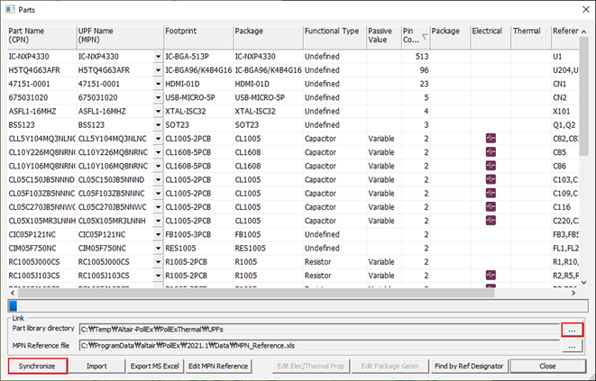
To open the parts dialog, select the Properties > Parts menu. The Parts Manager dialog displays.
Some of the properties, for example Part Name, UPF Name, Footprint, Package, Functional Type, Passive value, Pin Count, Package/Electrical/Thermal icon and Reference Designation display. The RLC values of passive component display automatically if they are defined in the CAD file.
In the Link field, you can assign the path of Part library directory and MPN Reference file.
The check mark at the Package, Electrical, and Thermal columns means that this component has Package/Electrical/Thermal information. All part information is assigned (linked) by two methods and will be stored in the Parts folder under the project directory.
