Mentor Graphics Interface

Mentor Graphics is releasing several different ECAD tools, PADS PowerPCB, Board Station, and Xpedition.

Mentor Graphics Board Station

PollEx PCB’s Mentor Graphics - Board Station reader uses the following five ASCII files:

File Example
comp.com_XXX comps.comp_256
net.net_XXX nets.net_123
traces.traces_XXX traces.traces_123
tech.tech_XXX Tech.tech_123
geometry file *.geom

In the Board Station working folder, there are four files, except Geometry file. Select a file with a header, comp, net, and trace and tech files with the highest revision number. It means they are the latest files. However, you do not need the tech.tech_XXX file if you did not use blind or buried via.

Extract Geometry Files in Board Station

  1. Open the Job file and launch librarian.
  2. From the menu bar, click File > Save > Save ASCII Geometries.
  3. Select All Geometries menu.
    The files are saved as *.geom files.

Read Mentor Graphics Board Station ASCII in PollEx PCB

From the menu bar, click File > Import ECAD > Mentor Graphics Board Station. The Import from MentorGraphics Board Station dialog opens.

The Import from MentorGraphics Board Station dialog contains the following sections:
  • Layer Set-Up: Specify the artwork layer name to recognize as COC Top and Bottom.
  • Board Type: Select reading board type.


    Figure 1.
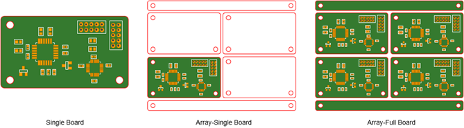
    • Single Board: Use this option for reading single board.
    • Array-Single Board: Use this option for reading array board contour and single board.
    • Array-Full Board: Use this option for reading array board contour and full single board.
  • Add Drawing Part to Reference Designator: Add drawing part to reference designator.
  • Exclude Silkscreen of 0 Line Width: Excludes silkscreen having a line width of zero.
  • Include Hatched Copper: Check this option if the hatched copper is used in the design.
  • Apply to Environment Setting: Apply settings to the environment setting.
  • ASCII Files: At any column if user selects one among five ASCII files, others are automatically assigned to each folder column. At this time, if there are multiple files having same name but different version, PollEx PCB will automatically select the latest version.
    • Read Sub-Board: Check this option when users use generic parts in array board and want them to be part of sub board.

Mentor Graphics Neutral File

PollEx PCB also can read Board Station’s neutral file and followings are necessary ASCII files for importing into PollEx PCB.
File Example
neutral_file neutral.vss
traces.traces_XXX traces.traces_123
tech.tech_XXX tech.tech_123
geometry file *.geom

If you did not use blind/buried via, the tech.tech_XXX file is not needed.

Import ASCII

From the menu bar, click File > Import ECAD > Mentor Graphics Neutral File. The Import from MentorGraphics Neutral File dialog opens.

Import from MentorGraphics Neutral File dialog contains the following sections:
  • Mode: Choose the type of ASCII file. Neutral files will read only component placement and netlist information. There is no routing information. On the other hand, whole files will read all PCB related information. When whole files is selected, PollEx PCB will read four files, tech.tech***, neutral, ASCII_GEOM., and trace.trace***.
    • Whole Files: Read all of files.
    • Neutral Only: Read the component section only.
  • Version: Choose the version Mentor Board Station or Mentor Xpedition.
  • Apply to Environment Setting: Apply settings to the environment setting.
  • ASCII Files: You can select necessary files individually.

Mentor Graphics Xpedition

PollEx PCB reads Mentor Graphics Xpedition’s six ASCII files. The following table shows all necessary files and their information.
File Name Description
Cell.hkp Component placement information
JobPrefs.hkp Layer information
Layout.hkp Routing information
NetProps.hkp Net information
Padstack.hkp Padstack information
PDB.hkp Part library information
  1. Extract ASCII file from Mentor Graphics Xpedition.
  2. From the menu bar, click File > Import ECAD > Mentor Graphics Xpedition.
    The Import from MentorGraphics dialog opens.
  3. In the Import from MentorGraphics dialog box:
    1. Import From: Choose which file format to import
      1. Xpedition Binary File: Select the target Binary file *.pcb to import.
      2. Xpedition ASCII File: Select the target ASCII files *.hkp to import.
    2. User Defined Settings: Apply settings to the environment setting.
      • Import Type: Select the file format to be imported. This is usually automated to sync with the Import from MentorGraphic Xpedition page.
      • ASCII Options
        • Read sub-board: Check this option when board is arrayed board.
        • ASCII File: If there is sub-board in array board, define the location of sub board file data.
        • Select Sub Board: Option to read the Sub Board.
        • Read only One for the Same Boards: Only read one board if there are same multiple boards.
        • Allow Broken Component: Check this option when user wants to convert reference-changed component to break component.
        • Allow Unconnected Net: Check this option when user wants to read unconnected net together.
        • Remove Net Data: Use this option when user wants to import design without routing information.
      • Layer Set-Up: Set Mentor Graphics layers’ name which will be used as PDB’s component related layers for Board outline, Panel outline, and Hole.
  4. After selecting all files, click Import to start reading Expedition into PollEx PCB.


    Figure 2.

Mentor Graphics PADS

You can export Mentor Graphics PADS design to an ASCII file, *.asc. Depending on the ASCII version of PowerPCB, they might be different, but PollEx PCB will support every version of them.

  1. Extract ASCII file from Mentor Graphics PADS.
  2. From the menu bar, click File > Import ECAD > Mentor Graphics PADS.
    The Import from MentorGraphics PADS dialog opens and contains the following sections:
    • Layer Set-Up: Layer Setting is optional. Specify artwork layer name per each menu.
      • COC Top/bottom: PollEx DFM will use these layers’ data for measure base.
      • Board Outline: If there is the specific layer for board contour, give that layer name. This layer will be transferred to layer number 21 in PDB structure.
      • Drill Layer: If there is the specific layer for drill, give that layer name. This layer will be transferred to layer number 22 in PDB structure.
      • Solder Mask To/Bottom: Specify the Solder Mask layer for top and bottom layers.
      • Metal Mask Top/Bottom: Specify the Metal Mask layer for top and bottom layers.
      • Silk Top/Bottom: Specify the Silk layer for top and bottom layers.
    • Signal Layer in Part Section: In footprint definition, enable this checkbox if object layer is signal layer.
    • Signal Layer in Line Data Section: In board figure definition, enable this checkbox if object layer is signal.
    • Level 0 is Board Outline: Enable this checkbox if layer level 0 is board contour layer.
    • Allow Broken Component: Enable this checkbox if Broken Component is used.
    • COC of 0 Line Width: Enable this checkbox if line width of COC as 0.
    • CAM Pad Over Size (Solder, Paste): Enable this checkbox if solder mask definition is recorded in CAM.
    • Generate Teardrops: This option is used automatically generated teardrop shape at PAD and Via.
    • Remove Duplicated Segments: Enable this checkbox to remove duplicated segments.
    • Apply to Environment Setting: Apply settings to the environment setting.
    • PADS ASCII File (*.asc): Select the target ASCII files *.asc to import.