General
In the General tab, set the board information, fiducial mark coordinates, and reference coordinates.
-
Board
-
Board Origin: Set the origin position of the underfill
coordinates.
Figure 1. 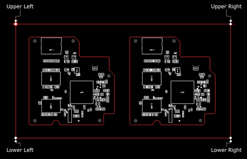
-
Number of Fiducial Mark: A fiducial mark list is created after entering
the fiducial mark quantity and clicking Apply.
Click Set Location and click the fiducial mark
location in the design. The X and Y coordinates are entered.
Figure 2. 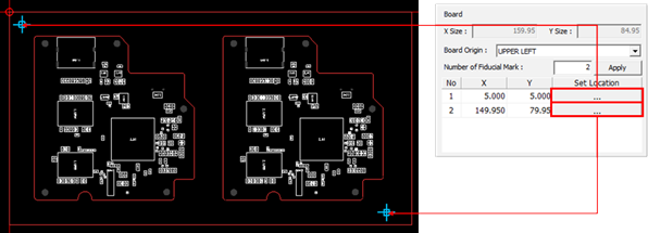
-
Board Origin: Set the origin position of the underfill
coordinates.
-
Base Location of Block
-
Set Component: Used when setting the base location by selecting a part
in the design data. When a part to be a reference is selected, the
center position of the same parts placed on each unit PCB is registered
as the reference coordinates. The component coordinates of the first
unit are used as the base location.
Figure 3. 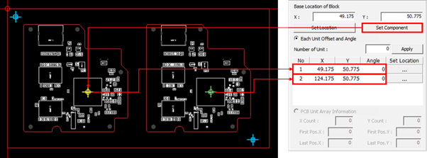
-
Set Component: Used when setting the base location by selecting a part
in the design data. When a part to be a reference is selected, the
center position of the same parts placed on each unit PCB is registered
as the reference coordinates. The component coordinates of the first
unit are used as the base location.
-
Parameter
- Click Load.
- Select import parameters used when creating the nozzle movement coordinate pattern of the underfill dispenser.
Figure 4. 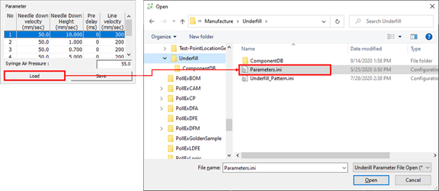
-
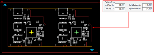
Pattern Area: Set the nozzle movement coordinate pattern area of the underfill
dispenser.
Figure 5.