Direct Generation - Result
Result Tab
- Top: Displays the result of top placed parts.
- Bottom: Displays the result of bottom placed parts.
- Top-Deleted: Displays the list of deleted parts among the parts placed on the top layer.
- Bottom-Deleted: Displays the list of deleted parts among the parts placed on the bottom layer.
Edit and Confirm
- Edit Mode: Can modify the part's coordinates and angle from the generated mounting coordinate data results.
- Set Mounting Part Code: Set mounting part code.
- Confirm: This button is applied after editing the coordinates and angle of the part in Edit Mode.
Result Table
- Reference Name: Refers to the reference name on the PCB design.
- Part Code: Refers to the part code.
- Mounting Part Code: Refers to the part code in Mounting Part Code Matching Table.
- X: Refers to X coordinate of part.
- Y: Refers to Y coordinate of part.
- Angle: Refers to angle of part.
- Property: Refers to part’s value in property.
- Result Information: Refers to comment of each result.
- Change to Alternative Component: Can replace part code to alternative part.
Save and Export
- Delete: Can delete the selected part.
- Export Block Data: Exports the mounting coordinate data of the sub board designated as a block as a text (*.txt) file.
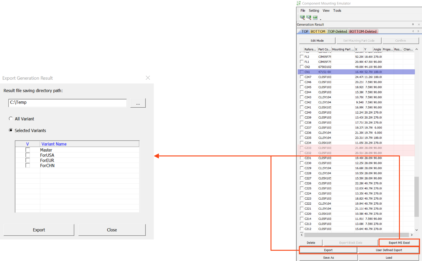
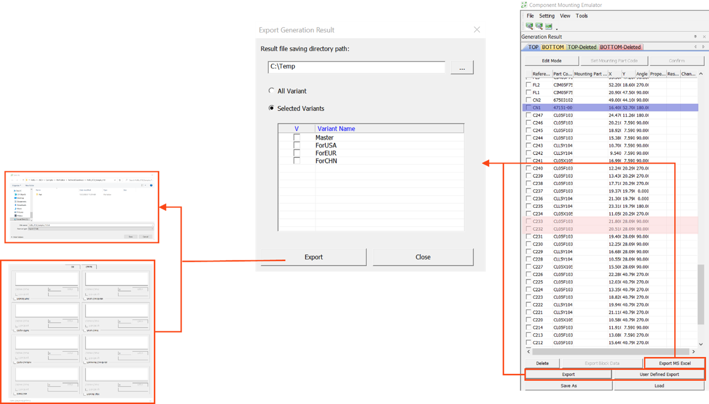
- Export MS Excel: Can export the generated result to Excel file through Direct Generation menu.
- Export: Mount data of the mounter format selected on the Direct Generation Setting screen can be exported.
- User Defined Export: Exports mount data in user defined
format.
- Board Size: Sets the information of board size.
- Title String: Sets the string for title.
- Column Count: Sets the number of columns.
- Table: Sets exporting format for each column.
- Origin Location: Sets exporting format for board origin.
- Title String: Sets the string for title.
- Column Count: Sets the number of columns.
- Table: Sets exporting format for each column.
- Origin Offset: Sets offset information of origin.
- Title String: Sets the string for title.
- Column Count: Sets the number of columns.
- Table: Sets exporting format for each column.
- Fiducial Mark: Sets exporting format for fiducial mark.
- Title String: Sets the string for title.
- Column Count: Sets the number of columns.
- Table: Sets exporting format for each column.
- Fiducial Light: Sets exporting information of fiducial light.
- Title String: Sets the string for title.
- Column Count: Sets the number of columns.
- Table: Sets exporting format for each column.
- Placement Coordinate: Sets exporting format for part placed
coordinates.
- Title String: Sets the string for title.
- Column Count: Sets the number of columns.
- Table: Sets exporting format for each column.
- Array Count: Sets exporting format for array board information of
sub board.
- Title String: Sets the string for title.
- Column Count: Sets the number of columns.
- Table: Sets exporting format for each column.
- Array Coordinate: Sets exporting format for each sub board’s
origin.
- Title String: Sets the string for title.
- Column Count: Sets the number of columns.
- Table: Sets exporting format for each column.
- OK: Saves the user-defined format Mount Data as a text (*.txt) file.
- Board Size: Sets the information of board size.
Click Save As to save the created part coordinate data (*.MEMD) file. Click Load to load the saved coordinate data (*.MEMD) file.
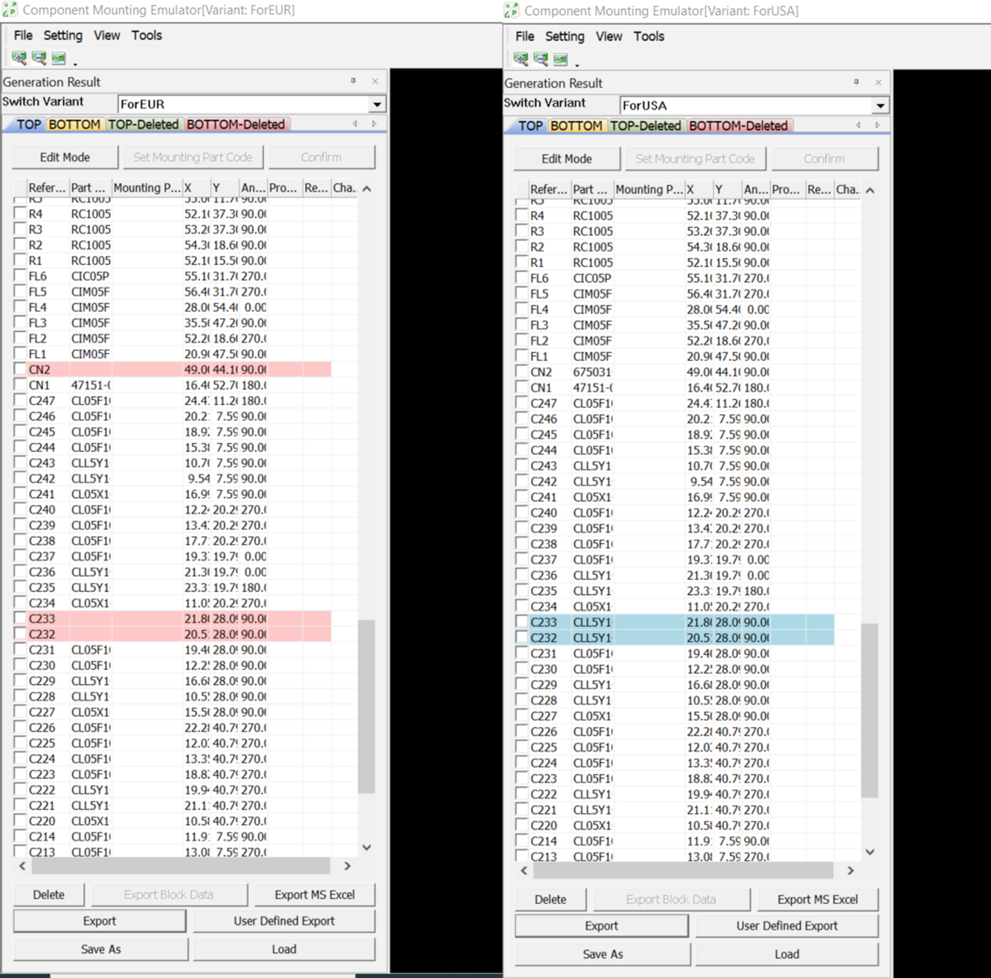
Switch Variant
From Generation result table, you can view the variant list by selecting the variant from the SWITCH VARIANT selection box.
For variant with an NP status the components name in the reference list is highlighted “Red”.

Export MS Excel: Can export the coordinate data for all Variants to Excel file.
Export: Mount data of the mounter format selected on the Direct Generation Setting screens for all Variants can be exported.
User Defined Export: Exports mount coordinate data for all Variants in user defined format.

