Define import data options in the Import Mount Data
dialog.
BOM: Can compare the matching status of part names between PCB and
BOM.
BOM + Mount Data: By using the Mount data from UPF library and BOM file,
can verify the inverse placement of the part and misalignment of the
coordinates. The UPF files will be loaded with mount data and part names
in the library and then comparing with BOM file which is imported by
user. The part names from UPF library will have a priority to use then
in BOM file. For example, the part name of U1 is different in mount data
and BOM file like below, UPF file which has same CPN (Company Part Name)
will be linked from the UFP library.
PCB: IC-NXP4330_PCB
Mount Data: IC-NXP4330_1
BOM: IC-NXP4330
Comparing by Reference Name: This function compares whether the
corresponding part exists in the BOM and mount data based on the
reference name on the PCB data, and whether the part name matches.
Mount Data List: Selects the mount data from the list. When loading the
mount data, 3D package information is output based on the coordinates
and angle of the mount data.
Note: The Mounting Emulator supports the
following mount data formats:
Panasonic: *.c88,
*.txt, plain text
(non-extension)
Fuji: *.crb,
*.pgo, *.job
Hanwha (Techwin): *.xml
ASM: *.txt
BOM
BOM Data: Selects the path of BOM file. 3D package shape will be
displayed by using part name from BOM. If there is no part name
in BOM, it is not displayed.
BOM Env: Defines the environment (*.EBI)
path to import BOM file.
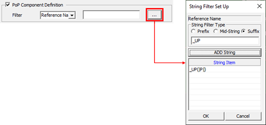
PoP Component Definition: For parts with high component densities, such
as mobile phones and digital cameras, a package on package (PoP) design
is sometimes applied. Option to check if the position of pin 1 of the
upper part of the PoP is the same as the position of pin 1 of the lower
part. The Filter is set through the string filter to recognize the top
part of the POP from the mount data.Figure 1. In Figure 1,
the part with the same reference name and the suffix _UP is recognized
as the top material of the PoP. For example, if U100 parts and U100_UP
parts exist in the mounting data, U100 parts are recognized as lower
parts and U100_UP parts as upper parts.
Allowable Distance specifies the allowable tolerance to be considered as
a pass when the coordinates of parts are wrong in the installation
verification. If the coordinate misalignment is greater than the entered
tolerance, the result is displayed in the Location Difference column of
the result list.
Mount Equipment chooses the type of mounting equipment. The information
such as offset, packing type which are related to each mounting
equipment will be used from UPF library.
Result - Top/Bottom.
The completed verifying result list is displayed on the left side of the
Component Mounting Emulator dialog.
You are able to review
components placed in the top and bottom tabs of the Mount Data list. Use the
Result Panel to search and review all checking results and correct the
incorrect part as exact angle.
BOM File: The part name from BOM file will be displayed on here. If
there is no matching part name from BOM, it will be shown as ‘Not
Exist’.
Reference Name: Can search the result by reference name.
Part Name: Can search the result by part name.
Correct Type/Correct All: Selects information to be corrected for
the selected part from the list of mounting verification results.
Pressing the Correct All button corrects the mounting data according
to the selected Correct Type.
All: Corrects Angle Difference, Location Difference of the
selected part.
Angle: Corrects Angle Difference of the selected part.
Location: Corrects Location Difference of the selected
part.
Table: Displays the list of verification results.
Ref Name: Exports Reference Name of part.
Part Name: Exports Part Name of part.
X: Exports X coordinate of part from mount data.
Y: Exports Y coordinate of part from mount data.
Angle: Exports angle of part from mount data.
Location Diff: Exports difference about X, Y coordinate
between 3D shape in UPF and footprint location.
Angle Diff: Exports difference about angle between 3D shape
in UPF and footprint location.
Result: Exports verification results.
No Mount Data: Mount data not in UPF library.
No_UPF: Matching file not in UPF library.
PKG_Type (None): Packing type like reel or tray is
not defined in UPF library.
Pin Name Mismatch: Pin name of part is not matched
between PCB design and UPF library.
NO_PKG: 3D shape not in UPF file.
Diff Part (PCB, BOM): Part name is different between
mount data and PCB design in having same reference
name.
Click Export to export a verification list
with the corrected angle and X, Y coordinate as same format of mount
data list.
The Export Mount Data dialog opens.
Mount Data List chooses target of corrected mount data for
exporting. File will be displayed in gray after getting
corrected one. Save Directory sets the save directory.
Click Export MS Excel to export the Result
Table in Excel format.