FF Card
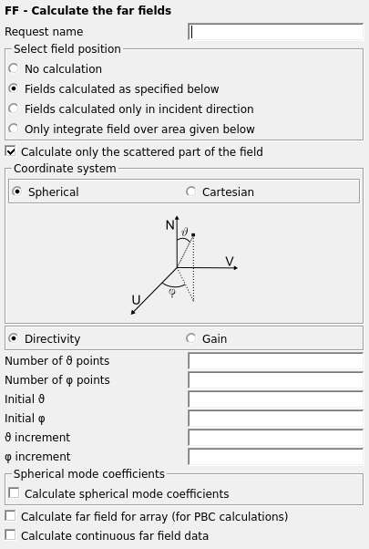
This card controls the calculation of the far fields in spherical or Cartesian coordinates.

Figure 1. The FF - Calculate the far fields dialog.
Parameters:
- Request name
- The name of the request.
- No calculation
- Disables the calculation.
- Fields calculated as specified below
- The far field is calculated with the specified settings.
- Fields calculated only in the incident direction
- The far field is calculated only in the incident direction (used, for example, to calculate monostatic RCS). The rotation and phase reference parameters of the incident plane wave (specified at the A0 card) are used for the field calculation.
- Only integrate field over area given below
- The far field is calculated but it is not written to the .out file in order to limit its size. This option is meaningful when the individual values of the field strength (such as directivity and gain) are not required, but the total radiated power has to be calculated from the integral of the Poynting vector (see the discussion below), or if only the modal coefficients are required. If a .ffe file has been requested with the DA card, the field values used in this integration will be written to the file.
- Calculate only the scattered part of the field
- When this item is checked, the field radiated by the impressed sources (such as Hertzian dipoles) is not included. Normally one would not check this item so that the total field is calculated. The total field includes all source contributions except plane wave sources.
- Coordinate system
- Select to use the spherical coordinate system ( , ) or a Cartesian grid (u, v) to define the far field request points.
- Directivity/Gain
- Select the required quantity.
- Number of /u points
- The number of observation points in the /u direction. An empty field will be set to 1.
- Number of /v points
- The number of observation points in the /v direction. An empty field will be set to 1.
- Initial /u
- The angle in degrees of the first observation point when using spherical coordinates, or the u component of the unit vector of the first observation point when using Cartesian coordinates.
- Initial /v
- The angle in degrees of the first observation point when using spherical coordinates, or the v component of the unit vector of the first observation point when using Cartesian coordinates.
- /u increment
- Increment in degrees of the angle when using spherical coordinates. Increment in u (unitless) when using Cartesian coordinates.
- /v increment
- Increment in degrees of the angle when using spherical coordinates. Increment in v (unitless) when using Cartesian coordinates.
- Calculate spherical mode coefficients
- Calculate the spherical mode coefficients of the far field.
- Specify number of modes
- When this option is unchecked, the number of modes is automatically determined when the spherical mode coefficients are computed. If this option is checked, the Maximum mode index N must be specified, which will affect the number of modes calculated.
- Maximum mode index N
- Specify the maximum number of modes to be calculated by means of the mode index.
- Calculate far field for array (for PBC calculations)
- Check this item if the far field is to be calculated for an array of elements. The Number of elements in direction (PE card) and the Number of elements in direction (PE card) should be specified if this option is chosen.
- Calculate continuous far field data
- Use interpolation to display continuous far field data.
When using the FF card with Number of points, , and Number of points, , both larger than 1, the Poynting vector is integrated over the two spherical segments as follows:
- and
- and
In the case of an antenna the power provided by the voltage sources must be equal to the radiated power over the whole sphere. The total radiated power can be calculated using for example the following commands:
** Far field integration in angular increments of #delta (in degrees)
#delta=5
#nt=180/#delta + 1
#np=360/#delta + 1
FF: 3 : #nt : #np : 0 : 0 : 0 : 0 : #delta : #delta
The output in the .out file then reads as follows:
Integration of the normal component of the Poynting vector in the
angular grid DTHETA =    5.00 deg. and DPHI =    5.00 deg. ( 2701 sample points)
  angular range THETA        angular range PHI       radiated power
 -2.50 .. 182.50 deg.      -2.50 .. 362.50 deg.     5.60499E-03 Watt
  0.00 .. 180.00 deg.       0.00 .. 360.00 deg.     5.52821E-03 Watt
If the model is symmetrical, it is not necessary to integrate over the full sphere. If there are three planes of symmetry (as for a simple dipole in free space) the integration only needs to be done over an eighth of the sphere. The power then has to be multiplied by 8.
If an infinite ground plane has been specified, the calculation of the far fields below the ground plane is not possible. Observation points with z < 0 will therefore be ignored.
Use the OF card to specify an offset for the coordinate system's origin used in far field calculations.