Reference Plane
This option shows the following panel on the right side of the window:
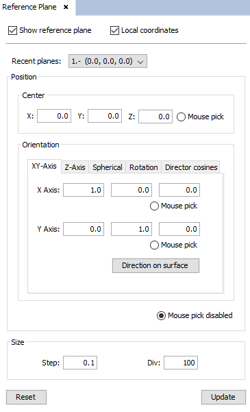
This panel allows the user to show a reference grid by selecting the center, orientation and resolution. It is especially useful for modeling geometry or placing elements, as it may be used as a local coordinate system.
All the options available in the Reference Plane panel are listed in the following:
The Show reference plane option paints or hides the current configuration of the reference plane.
When the Local coordinates check box is enabled, the local coordinate system defined by the reference plane is considered for new geometrical operations. Disable this option to work with the default Cartesian coordinate system.
All the previous different coordinate systems are listed in the Recent planes section. The reference plane is updated when an element of the list is selected, by using the current Step and Div parameters.
- The position section gathers the parameters required for the new local coordinate system.
- The options Mouse pick may be used to load the adjacent fields from the next clicked point on the geometry.
- The Center fields define the position where the reference plane is centered.
- The option Mouse pick disabled option deactivates the fields load from the mouse click events on the geometry.
- The Orientation subsection contains multiple ways for defining the coordinate system of the reference plane. The next options are available:
-
- XY-Axis
The direction of the X and Y axes must be specified. Note that the directions are defined starting from the center position.
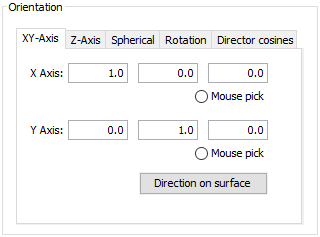
The Direction on surface button search the closest point to the specified Center on the selected surfaces. The positions parameters of the reference plane are directly loaded to generate a plane centered on the closest point on the surface that is tangent, i. e., the Z axis of the new reference plane is the normal vector of the surface at the center point.
- Z-Axis
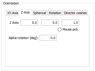
The reference plane is normal to the specified Z axis. Once the plane is defined, it also may be rotated by specifying the Alpha rotation angle, in degrees.
- Spherical
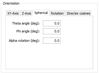
The reference plane orientation is defined in spherical coordinates with the Theta and Phi angles, and also may be rotated with the Alpha rotation.
- Rotation
The reference plane is defined by applying the X, Y and Z rotation angles, centered at the specified position.
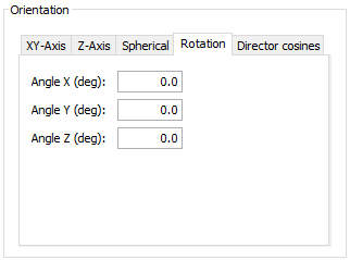
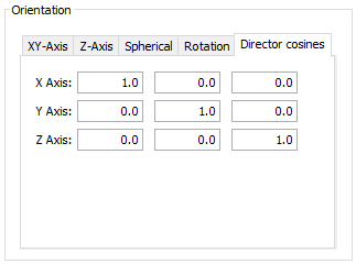
- Direction cosines
The reference plane’s coordinate system is directly defined by its rotation matrix.
The Size section allows to change the resolution and size of the reference plane. Note that the reference plane is always a square grid, so the Size properties affects both directions of the plane.
- The Step parameter modifies the length of all divisions.
- The Div parameter changes the number of divisions.
The Update button repaints the new reference plane with the last updated parameters.
The Reset button restores all the default parameters of the Reference Panel, so it is placed at the XY plane and centered at the origin.