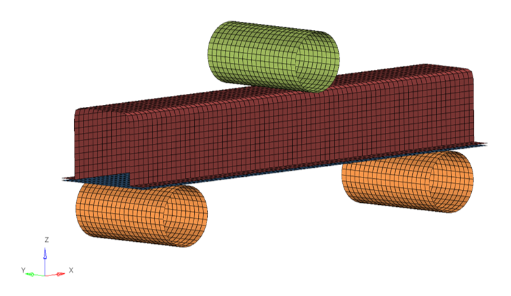
Tutorial Level: Intermediate This tutorial demonstrates how to set up a 3-point bending model consisting of a head
profile and a closing plate.
This validation test is a common test to determine the bending strength during
bending load. The usage of the head profile structures is a common design feature in
automotive and aero industry.Figure 1.
In this lesson you will learn to:
Step 1: Load the initial model
Step 2: Define material
Step 3: Define property
Step 4: Solid spotweld creation
Step 5: Define Failure /FAIL/CONNECT
Step 6: Create rigid body
Step 7: Create boundary conditions
Step 8: Create imposed velocity
Step 9: Set contact
Step 10: Define time history output
Step 11: Create Engine setup
Step 12: Export solver deck and run model
Step 13: Check results
Model Description
The model set up consists of:
Material creation (with strain curve creation) and assignment:
Elasto-plastic material /MAT/LAW36 (plastic):
[Rho_I] Initial density = 7.85e-09 (ton/mm3)
[nu] Poisson’s ratio = 0.29
[E] Young’s modulus = 210000 (MPa)
UNITS: Length (mm), Time (s), Mass (t)
Simulation time: [0 – 7.01E-02]
Boundary Conditions: The supports are all fixed. An imposed velocity of
1000.0 mm/s is applied on the impactor.
Model size: 370mm x 46.5mm x 159mm
Prerequisites
To run this simulation, you will need access to a licensed version of Radioss. You will need an internet connection to watch the
video tutorials and download the files.
Model Files
Before you begin, copy the file(s) used in this tutorial to your
working directory.