Stick models are generally used to simplify the representation of an aircraft for
aeroelastic analysis.
Preprocessing is done using Altair HyperWorks
in the OptiStruct user profile. A structural stick model
with existing data is used as a base model and this tutorial demonstrates the
creation of entities in the Aeroelasticity domain.
The following exercises are included:
Create Panels (CAERO1)
Create interpolation splines (SPLINE2)
Create rigid body motions for aeroelastic TRIM variables (AESTAT)
Define TRIM variables
Submit the job
View the results
Launch HyperMesh
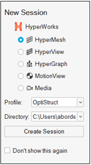
Launch HyperMesh.
In the New Session window, select HyperMesh from the list of tools.
For Profile, select OptiStruct.
Click Create Session.
Figure 1. Create New Session This loads the user profile, including the appropriate template, menus,
and functionalities of HyperMesh relevant for
generating models for OptiStruct.
Import the Model
On the menu bar, select File > Import > Solver Deck.
In the Import File window, navigate to and select
aeroelasticity_trim_wing_stick.bdf you saved to your
working directory.
Click Open.
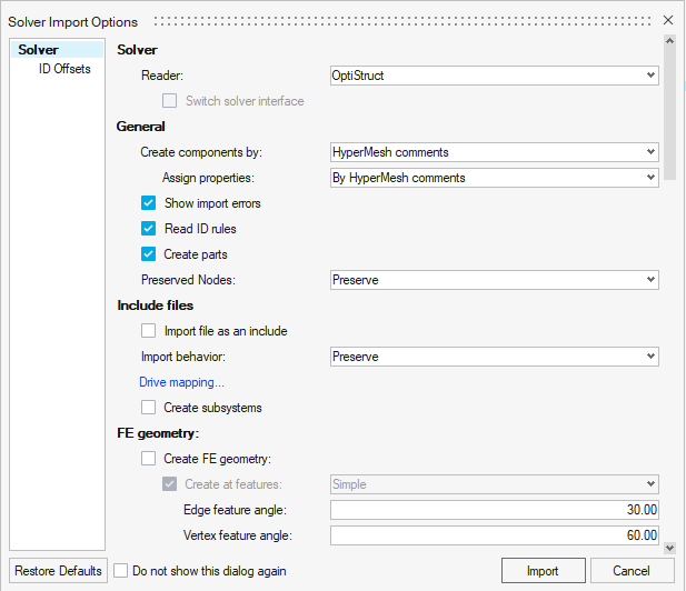
In the Solver Import Options dialog, ensure the Reader is
set to OptiStruct.
Figure 2. Import Base Model in HyperMesh
Accept the default settings and click Import.
Tip: Alternatively, you can drag and drop the file from your file
browser into the application window to open the model file.
The base structural stick model is loaded in HyperMesh. The model is comprised of CBAR elements.Figure 3. Base Structural Model of Aircraft Wing Stick Model
Open the Aeroelasticity Browser
The Aeroelasticity Browser is useful for upcoming tasks in this
tutorial. If the Aeroelasticity is not already on your
menu bar, click View > Ribbons > Aeroelasticity to add it.
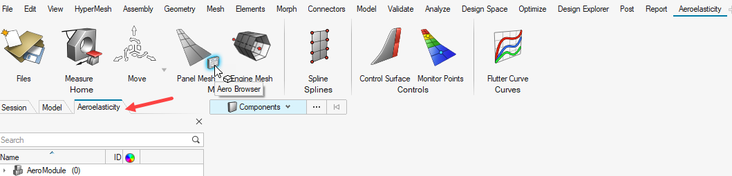
On the menu bar, click
Aeroelasticity.
On the Aeroelasticity ribbon, hover over any tool group
and click the satellite icon that appears.
The Aeroelasticity Browser opens.Figure 4. Access the Aeroelasticity Browser
Set Up the Model
Create AEROS Entry
In this step, basic/reference parameters for the simulation are defined through
AEROS.
Right-click on the Aeroelasticity Browser and select Create > Controls > AEROS.
A default collector for AEROS is
created.
In the Aeroelasticity Browser, expand
AeroModule.
Click on the AEROS collector.
For REFC (Reference chord length), enter 0.1.
For REFB (Reference span), enter 0.55.
For REFS (Reference wing area), enter 0.055.
Figure 5. Definition of AEROS
Create Grid Points around the Stick Model
Since the base structural model is a stick representation, grid points are created
around the stick model as corner points of the panel mesh.
On the menu bar, click
Topology.
On the ribbon, click the Create Points and Nodes
tool.
Figure 6. Create Points
Left click anywhere in the modeling window.
The grid coordinate window opens.
Specify the grid coordinate values, then left-click outside the grid coordinate
micro-dialog.
Use this method to create four grid points using the following
coordinates:
Table 1. Coordinates of Grid Points
Grid Point
X
Y
Z
1
0.0
0.0
0.0
2
0.1
0.0
0.0
3
0.1
0.55
0.0
4
0.0
0.55
0.0
Figure 7. Create Grid Points
Right click and exit the tool.
Figure 8. Grid Points around Stick Model
Create Aeroelasticity Panels
The CAERO1 entry is used to create aeroelasticity panel mesh in
the base structural model.
On the Aeroelasticity ribbon, Aero Meshing tool group,
click the Panel Mesh tool.
Figure 9.
Select the Transparent check box.
The points surrounding the structural model are displayed.Figure 10. Open Panel Mesh Tool
Select the end points of the CAERO1 panel mesh so that node
1 and node 4 are along the span direction and node 1 and 2 are along the chord
direction. For more information, refer to CAERO1.
Figure 11 shows the
correct selection order.Figure 11. Grid Point Selection for CAERO1 Definition
In the microdialog that appears, for Span enter 10.
Press Enter to confirm.
For Chord, enter 5. Press Enter to confirm.
Click .
Figure 12. Specify Span and Chord Values in CAERO1 Definition
The panel mesh is created.
Click to exit the tool.
Figure 13. Aeroelastic Panel Mesh for the Problem
Create Interpolation SPLINES
In this step, a SPLINE2 entry is created for interpolating motion
and/or forces between the aeroelastic and structural domain. The
SPLINE2 entry refers to the panels (aeroelastic domain), a
node-set (structural domain) and the corresponding CAERO1 entry.
The node-set for the structural domain is already available in the base model.
On the Aeroelasticity ribbon, click the
Spline tool.
Figure 14.
The SPLINE2 creation tool opens.
Click the icon.
For Spline type, select Linear_Spline_2 from the
drop-down menu.
Figure 15. Selection of Linear Spline (SPLINE2)
Reference the aero panels.
In the Aero drop-down menu, select
Elements.
Figure 16. Element Based Selection in Aero Domain
On the model, select the aero panels.
Figure 17. Selection of Aero Panels on Model
Reference the node-set.
In the Structure drop-down menu, select
Sets.
Figure 18. Set Based Selection in Structural Domain
Click .
In the Advanced selection dialog, select SET1
(structural domain set).
Figure 19. Selection of Structural Node Set
Click OK.
Reference the CAERO1.
Next to Component, click .
In the dialog, select the CAERO1 previously
created.
Figure 20. Selection of CAERO1 Entry
Click OK then to exit the tool.
Under the Splines section of the Aeroelasticity Browser, right-click and select
Rename.
Enter the name SPLINE2.
Reference the existing coordinate system.
For CID, click and select .
In the dialog, select the existing coordinate system.
The AESTAT entry specifies rigid body motions which are used as
trim variables in the aeroelastic analysis. This is later referenced in the
TRIM Bulk Data Entry.
In the Aeroelasticity Browser, right-click on
Controls and select Create > AESTAT.
The AESTAT collector is created.
For Name, enter ANGLEA_AESTAT.
For Label, select ANGLEA from the drop-down list.
A Degree of Freedom (DoF) for Angle of Attack is created.Figure 22. Definition of AESTAT
Define TRIM Entry
In this step, the Mach number, Dynamic pressure, and constraint values for the
aerodynamic trim variables are defined.
In the Aeroelasticity Browser, right-click and select Create > Loads > TRIM.
For Name, enter TRIM ANGLEA 0.1 RAD1.
For Q (Dynamic pressure), enter 1500.0.
For NUM_LABEL, enter 1.
Reference AESTAT.
Under TRIM1, for LABEL, click and select .
In the Advanced Selection dialog, choose
ANGLEA_AESTAT.
Figure 23. Reference AESTAT in TRIM Entry
Click Click OK.
For UX, enter 0.1.
The angle of attack is constrained to 0.1 radians.Figure 24. Definition of TRIM Entry
Reference the TRIM Entry in the Subcase
In this step, the TRIM entry is referenced in the subcase.
In the Aeroelasticity Browser, select the
TRIM_ANALYSIS subcase.
Under Subcase Definition, for Analysis type select Static
Aeroelastic Response from the drop-down menu.
For TRIM, click and select .
In the Advanced Selection dialog, choose TRIM ANGLEA 0.1
RAD1.
Click OK.
Figure 25.
Under SUBCASE OPTIONS, for Analysis TYPE, select SAERO
from the drop-down menu.
Export the Input File
In this step, the input file is exported to the working directory. This file is later
solved using OptiStruct as the solver.
From the menu bar, click File > Export > Solver Deck.
Enter a name for the file.
Click Save.
The Solver Export Options dialog
opens.
In the dialog, accept the default options.
Click Export.
The file is now available in your working directory.Figure 26.
Submit the Job
The Altair Compute Console (ACC) is used to submit the job.
In the Windows Start menu, select Start > Altair2026 > Compute Console.
For Input file, use to browse your working directory for the desired
file.
Click Open.
For Options, click .
In the Select Solver Options dialog, click the
-nt check box.
Enter 4 for the argument.
Click OK.
Click the -out check box.
Click Apply Selected.
Click Close.
Click Run.
If the job is successful, the new results files should be in the working
directory. If any errors are present, look in the
aeroelasticity_trim_wing_stick.out file for error
messages that could help debug the input deck.
View the Contour Plot
The following steps describe how to review the results in HyperView.
HyperView is a complete post-processing and visualization
environment for finite element analysis (FEA), multi-body system simulation, video,
and engineering data.
After you receive the analysis completion message, click
Results.
In HyperView, click the Contour panel button .
For Result type, select Displacement (v) from the first
drop-down menu.
Select Mag from the second drop-down menu.
Click Apply.
The resulting contour represents the displacement field for the
aeroelastic trim analysis.
Figure 27. Displacement Contour Plot of Wing Stick Model


 .
.

 to exit the tool.


 icon.
icon.


 .
.


 to browse your working directory for the desired
file.
to browse your working directory for the desired
file.
 .
.
 .
.
