OS-HM-T: 3020 NLSTAT Analysis of Solid Blocks in Contact
Tutorial Level: Beginner This tutorial demonstrates nonlinear implicit small displacement analysis in OptiStruct involving elasto-plastic materials, contact, and
continuing the nonlinear solution sequence from a preceding nonlinear loadcase.
Before you begin, copy the file(s) used in this tutorial to your
working directory.
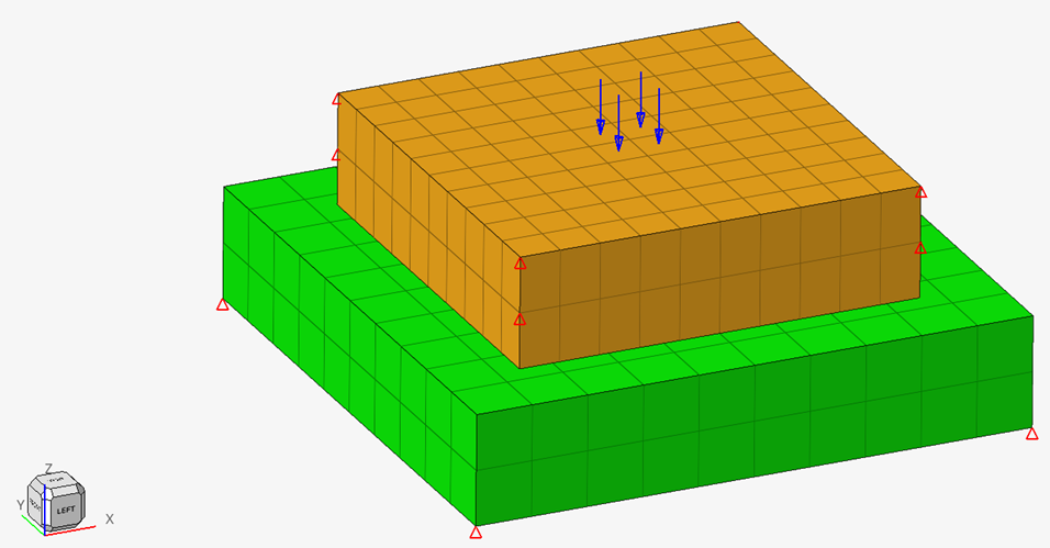
Figure 1 illustrates the structural model used for this tutorial, which is two square
solid blocks made of elasto-plastic steel material. The dimensions of the blocks and
the material parameters can be obtained in the table below.
In the first nonlinear subcase, pressure loading is applied to the top solid block,
the top corners of which are constrained in the X and Y directions. The top solid
is in contact with the bottom solid, the bottom corners of which are constrained in
the X, Y, and Z directions. The second nonlinear subcase is to simulate the
unloading and is a continuation of the nonlinear solution sequence from the previous
loading subcase. Figure 1. Model and Loading Description
Table 1. Parameters
Units
Length: mm
Time: s
Mass:
Mgg
Force: N
Stress: MPa
Top Block
72 mm x 72 mm
Bottom Block
100 mm x 100 mm
Thickness of Blocks
20 mm
Material
Steel, Elasto-plastic
Initial Density (⍴): 7.90e-9 kg/mm3
Young's Modulus (E): 210000 MPa
Poisson's Coefficient (v): 0.3
Yield Stress (σ0): 850.0 MPa
Imposed Pressure
1000.0 MPa, applied at the center of the top
block
The following exercises are included:
Create elasto-plastic material
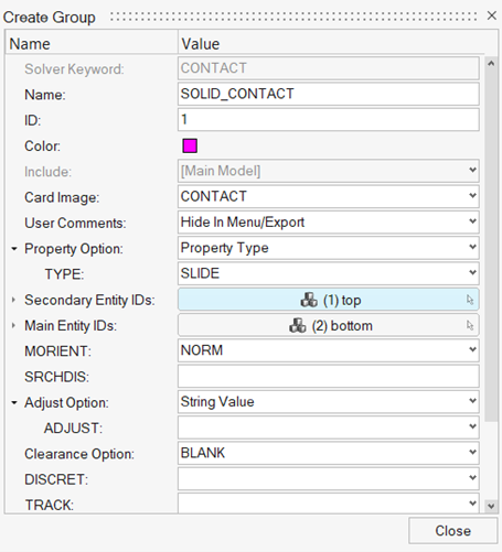
Define contact between the two blocks
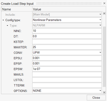
Define nonlinear implicit parameters
Set up NLSTAT analysis for the first subcase (loading)
Set up NLSTAT analysis for the second subcase (unloading)
Submit job and view result
Launch HyperMesh
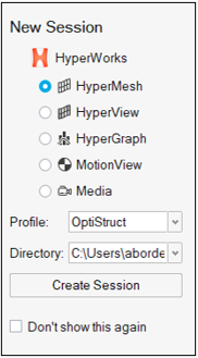
Launch HyperMesh.
In the New Session window, select HyperMesh from the list of tools.
For Profile, select OptiStruct.
Click Create Session.
Figure 2. Create New Session This loads the user profile, including the appropriate template, menus,
and functionalities of HyperMesh relevant for
generating models for OptiStruct.
Import the Model
On the menu bar, select File > Import > HyperMesh Model.
Navigate to and select nlstat.hm.
Click Import.
Set Up the Model
Create the Elasto-plastic Material
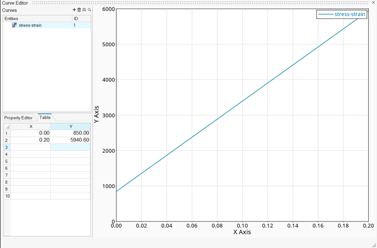
First, the stress versus plastic strain curve for the material needs to be
defined.
In the Model Browser, right-click and select
Create > Curve.
A new window of the Curve Editor opens.
For Name, enter stress-strain.
Enter the following values for (x, y) in the pop-up window.
(x1, y1) = (0.00, 850.00)
(x2, y2) = (0.20, 5940.60)
Figure 3. Create Stress-strain Curve
In the Model Browser, under Curves, select the
stress-strain curve.
Click Color and select a color from the palette.
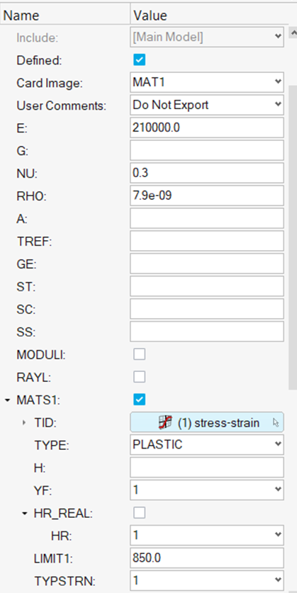
To update the elasto-plastic material, in the Model Browser select the material
steel.
The Entity Editor opens.
Selet the MATS1 check box to define elastic-plastic
material.
For TID, select Unspecified > Curves.
In the Select Curves dialog, select the
stress_strain curve and click
OK.
Input the following values in the editor.
E = 210000.0
NU = 0.3
RHO = 7.9e-09
TYPE = PLASTIC
YF = 1
HR = 1
LIMIT = 850.0
TYPSTRN = 1
TYPSTRN of 1 specifies stress (Y) versus strain (X).Figure 4. Define Elastic-Plastic Material
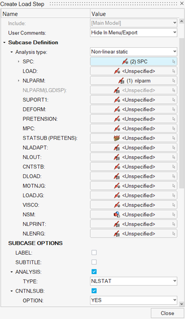
In the Model Browser, right-click and select
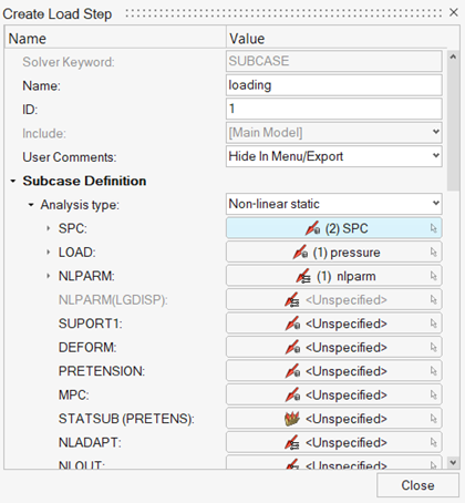
Create > Load Step.
For Name, enter loading.
For Analysis type, select Non-linear static from the
drop-down menu.
For SPC, click Unspecified > Loadcol.
From the dialog, select SPC from the list of load
collectors and click OK.
For LOAD, click Unspecified > Loadcol.
From the dialog, select pressure from the list of load
collectors and click OK.
For NLPARM, click Unspecified > Load step inputs.
From the dialog, select nlparm from the list of load
step inputs and click OK.
Click Close.
Figure 8. Create Loading Subcase
Create the Second Nonlinear (Unloading) Subcase
In the Model Browser, right-click and select
Create > Load Step.
For Name, enter unload.
For Analysis type, select Non-linear static from the
drop-down menu.
For SPC, click Unspecified > Loadcol.
From the dialog, select SPC from the list of load
collectors and click OK.
For NLPARM, click Unspecified > Load step inputs.
From the dialog, select nlparm from the list of load
step inputs and click OK.
Select the CNTNLSUB check box and set the option to
Yes.
Click Close.
Figure 9. Create Unloading Subcase
Define Output Control Parameters
In the Model Browser, right-click and select Create > Cards > Output.
Under CONTF, DISPLACEMENT, and STRESS, set Option to
Yes.
Under STRAIN, set EXTRA to PLASTIC.
Click Close.
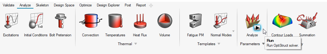
Submit the Job
Run OptiStruct.
From the Analyze ribbon, click Run OptiStruct
Solver.
Figure 10. Select Run OptiStruct Solver
Select the directory where you want to write the OptiStruct model file.
For File name, enter nlstat_complete.
The .fem filename extension is the recommended extension
for Bulk Data Format input decks.
Click Save.
Click Export.
For export options, toggle all.
For run options, toggle analysis.
For memory options, toggle memory default.
In the Altair Compute Console, click
Run.
If the job is successful, an "OptiStruct Job Completed" message appears
in the Compute Console Solver View Message Log. New results
files are in the directory where the model file was written. The
nlstat_complete.out file is a good
place to look for error messages that could help debug the input deck if any
errors are present.
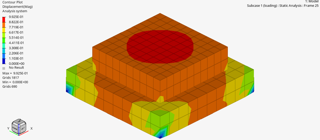
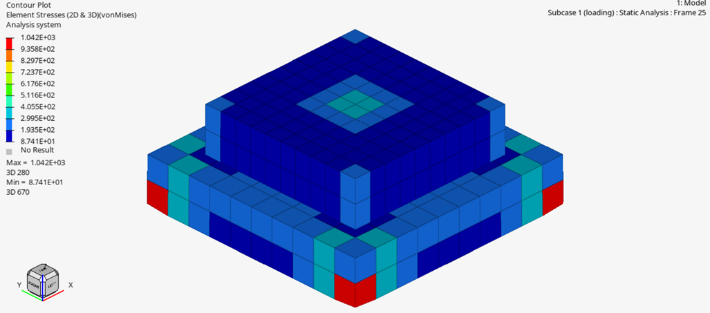
View Results
Launch HyperView.
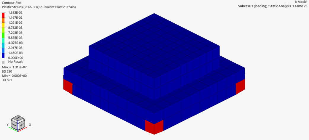
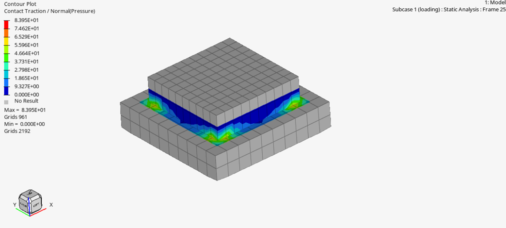
Plot the Displacement, the von Mises stress, plastic strains and contact
pressure contours at the end of the first (loading) step.
Figure 11. Contour of Displacements in Blocks Subject to Loading Figure 12. Contour of von Mises Stress in Blocks Subject to Loading Figure 13. Contour of Plastic Strains in Blocks Subject to Loading Figure 14. Contour of Contact Pressure in Block Interface after the First
(Loading) Subcase
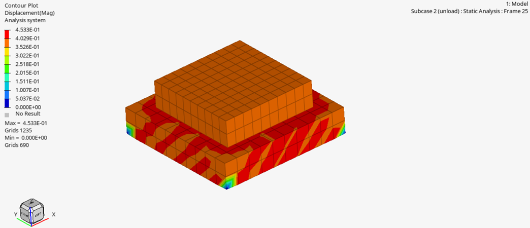
Change the subcase to the second (unloading) subcase and plot the displacement
contour to see the change in displacements in the blocks subject to
unloading.
Figure 15. Contour of Displacements in Blocks Subject to Unloading in Second
Subcase