OS-HM-T: 3000 Rubber Ring Crush and Slide using Self-Contact
Tutorial Level: Intermediate This tutorial demonstrates self-contact used in this nonlinear large displacement implicit
analysis with hyperelastic material and contacts using OptiStruct.
Before you begin, copy the file(s) used in this tutorial to your
working directory.
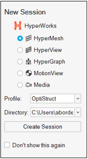
In the New Session window, select HyperMesh from the list of tools.
For Profile, select OptiStruct.
Click Create Session.
Figure 2. Create New Session This loads the user profile, including the appropriate template, menus,
and functionalities of HyperMesh relevant for
generating models for OptiStruct.
Import the Model
On the menu bar, select File > Import > Solver Deck.
In the Import File window, navigate to and select
rubber_ring_input.fem you saved to your
working directory.
Click Open.
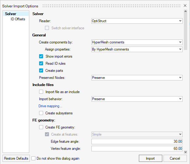
In the Solver Import Options dialog, ensure the Reader is
set to OptiStruct.
Figure 3. Import Base Model in HyperMesh
Accept the default settings and click Import.
Tip: Alternatively, you can drag and drop the file from your file
browser into the application window to open the model file.
Set Up the Model
Define the Hyperelastic Material
In the Model Browser, right-click and select
Create > Material.
For Name, enter hyper_elastic.
Click Color and
select a color from the color palette.
For Card Image, select MATHE from the drop-down
menu.
For MODEL, select ABOYCE from the drop-down menu.
For NU (Poisson's ratio), enter 0.495.
For RHO, enter 1.11e-09.
For TEXP, enter 0.000165.
Use the provided TABLES1 curves to define the stress strain curves for
tension-compression, equi-biaxial tension, and pure shear.
For TAB1, select Unspecified > Curves and select uniaxial in the
dialog.
For TAB2, select Unspecified > Curves and select biaxial in the
dialog..
For TAB4, select Unspecified > Curves and select planar_shear in the
dialog..
Click Close.
Create Properties
In this step, properties are defined and the component collector for the hyperelastic
material is updated.
In the Model Browser, right-click and select
Create > Property.
For Name, enter hyper_elastic.
For Card Image, select PSOLID from the drop-down
menu.
For Material, click Unspecified > Material.
In the dialog, select hyper_elastic from the list of
materials and click OK.
In the Component Browser, click on the Wheel
component.
For Property, select Unspecified > Property.
In the dialog, select hyper_elastic from the list of
properties and click OK.
The component Wheel has been updated with a property of the same name
and is the “Current Component." The material hyper_elastic is referenced by this
component.
Create the PCONT Property
In this step, the properties for both self-contact and surface to surface contacts
are defined.
In the Model Browser, right-click and select
Create > Property.
For Name, enter Contact.
For Card Image, select PCONT from the drop-down
menu.
Select the GPAD_OPT check box and for GPAD, select
NONE.
For STIFF, select HARD from the drop-down menu.
For MU1, enter 0.3.
In the Model Browser, right-click and select
Create > Property.
For Name, enter self_contact.
For Card Image, select PCONT from the drop-down
menu.
Select the GPAD_OPT check box and for GPAD, select
NONE.
For STIFF, select AUTO from the drop-down menu.
For MU1, enter 0.3.
Click Close.
Create Set Segments
In this step, set segments are defined which are later used to define the contact
groups.
In the Model Browser, right-click and select
Create > Set Segment.
For Name, enter Top.
For Elements, select 0 Elements > Elements.
In the dialog, select Top from the list of
components.
The shell faces are created on the Top component.
Select the FACE_FORMAT check box.
Click Close.
Similarly, create a set segment for the Base component.
In the Model Browser, right-click and select
Create > Set Segment.
For Name, enter Base.
For Elements, select the Base component.
Select the FACE_FORMAT check box.
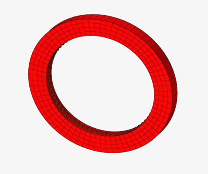
Create a contact set segment for the inner surface of the wheel.
In the Model Browser, right-click and select
Create > Set Segment.
For Name, enter Rubber_inner.
For Elements, select 0 Elements > Faces.
Select the inner surface of the Wheel component and click .
Figure 4. Shell Faces Created on Inner Surface of Wheel
Select the FACE_FORMAT check box.
Click Close.
Create a contact set segment for the outer surface of the wheel.
In the Model Browser, right-click and select
Create > Set Segment.
For Name, enter Rubber_outer.
For Elements, select 0 Elements > Faces.
Select the outer surface of the Wheel component and click .
Select the FACE_FORMAT check box.
Click Close.
Create Contact Groups
In the Model Browser, right-click and select Create > Group.
For Name, enter Top_rubber.
For Card Image, select Contact.
For Property Option, select Property Id.
For PID, select Unspecified > Property and select Contact from the list of
properties.
For Secondary Entity IDs, select Unspecified > Set and select the Rubber_outer set
segment.
For Main Entity IDs, select Unspecified > Set and select the Top set segment.
For MORIENT (contact orientation), select NORM.
For DISCRET, select N2S (node to surface).
For TRACK, select CONSLI.
Click Close.
Create another contact group.
For Name, enter Bottom_rubber.
For Card Image, select Contact.
For Property Option, select Property Id.
For PID, select Unspecified > Property and select Contact from the list
of properties.
For Secondary Entity IDs, select Unspecified > Set and select the Rubber_outer set
segment.
For Main Entity IDs, select Unspecified > Set and select the Base set
segment.
Set all other parameters to match the Top_rubber contact group.
Click Close.
Create a third contact group to define self-contact for the inner surface of
the ring.
For Name, enter self_contact.
For Card Image, select Contact.
For Property Option, select Property Id.
For PID, select Unspecified > Property and select self_contact from the
list of properties.
For Secondary Entity IDs, select Unspecified > Set and select the Rubber_inner set
segment.
For MORIENT (contact orientation), select
NORM.
For DISCRET, select S2S (surface to
surface).
For TRACK, select CONSLI.
Click Close.
Apply Loads and Boundary Conditions
Create the SPC for the First Load Step
In the Model Browser, right-click and select
Create > Load Collector.
A default load collector displays in the Entity Editor.
For Name, enter spc_top1.
On the menu bar, select the
Analyze ribbon.
On the ribbon, select BCs > Constraints.
Figure 5.
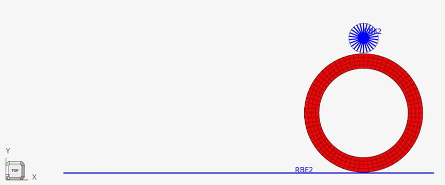
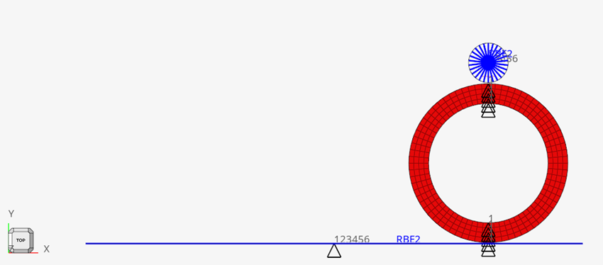
On the Constraints panel, select node 2269,
corresponding to the Top component.
Assign boundary conditions for the first load step (compression).
Select the check boxes for dof1,
dof3, dof4,
dof5, and dof6.
Click create.
Clear the previous check boxes and select
dof2.
In the dof2 text box, enter -6.44.
This assigns a displacement magnitude of 6.44 in the negative
y-direction.
Click create.
Click return.
Create the SPC for the Second Load Step
In the Model Browser, right-click and select
Create > Load Collector.
For Name, enter spc_top2.
On the menu bar, select the
Analyze ribbon.
On the ribbon, select BCs > Constraints.
Figure 6.
On the Constraints panel, select node 2269,
corresponding to the Top component.
Assign boundary conditions for the second load step (compression with
sliding).
Select the check boxes dof3,
dof4, and dof5 and
click create.
Clear the previous check boxes and select dof1,
dof2, and dof6.
For dof1, enter -13.000.
For dof2, enter -6.44.
For dof6, enter -10.44.
Click create.
Click return.
Create SPCs for the Base Wheel
In the Model Browser, right-click and select
Create > Load Collector.
For Name, enter SPC_base_wheel.
In the Component Browser, right-click on the Wheel
component and select Isolate.
On the menu bar, select the
Analyze ribbon.
On the ribbon, select BCs > Constraints.
Figure 7.
On the Constraints panel, select nodes > displayed.
Select the dof3 check box and click
create.
Click return.
Create a second load collector.
In the Model Browser, right-click and select
Create > Load Collector.
For Name, enter SPC_base_wheel_2.
Open the Constraints panel.
In the Model Browser, select the line of nodes
on the front face.
Figure 8. Apply Constraints to Wheel and Base
Select the dof1 check box and click
create.
Select node 2266 on the Base component.
Select all dof check boxes and click
create.
Click return.
Create the SPC for the Base Component
In the Model Browser, right-click and select
Create > Load Collector.
For Name, enter SPC_base.
On the menu bar, select the
Analyze ribbon.
On the ribbon, select BCs > Constraints.
Figure 9.
On the Constraints panel, select node 2266,
corresponding to the Base component.
Select all dof check boxes and click create.
Click return.
Create SPCADD Load Collectors
In the Model Browser, right-click and select
Create > Load Collector.
For Name, enter SPCADD1.
For SPCADD_Num_Set, enter 3.
For Loadcol list, select 0 Loadcols > Load Collectors and select spc_top1,
SPC_base_wheel_2, and
SPC_base_wheel from the list of load
collectors.
Click OK, then Close.
Create a second SPCADD load collector.
In the Model Browser, right-click and select
Create > Load Collector.
For Name, enter SPCADD2.
For SPCADD_Num_Set, enter 3.
For Loadcol list, select 0 Loadcols > Load Collectors and select spc_top2,
SPC_base_wheel, and
SPC_base from the list of load
collectors.
Click OK, then
Close.
Define Nonlinear Analysis Parameters
In the Model Browser, right-click and select
Create > Load Step Inputs.
For Name, enter NLPARM.
For Config type, select Nonlinear Parameters from the
drop-down menu.
For Type, NLPARM is auto-selected.
For NINC, enter 2000.
For MAXITER, enter 25.
For CONV, select UPW from the drop-down menu.
For EPSU, enter 0.001.
FOR EPSP, enter 0.001.
For EPSW, enter 1e-11.
Click Close.
Define NLADAPT Load Step Inputs
In the Model Browser, right-click and select
Create > Load Step Inputs.
For Name, enter NLADAPT1.
For Config type, select Time step Parameters from the
drop-down menu.
For Type, NLADAPT is auto-selected.
Select the DTMAX check box and for VALUE, enter
0.1.
Select the DTMIN check box and for VALUE, enter
1e-06.
Click Close.
Create a second NLADAPT load step input.
In the Model Browser, right-click and select
Create > Load Step Inputs.
For Name, enter NLADAPT2.
Select the DTMAX check box and for VALUE, enter
0.025.
Select the DTMIN check box and for VALUE, enter
1e-06.
Click Close.
Define the CNTSTB Load Collector
In the Model Browser, click Create > Load Collector.
For Name, enter CNTSTB.
For Card Image, select CNTSTB from the drop-down
menu.
For S1, enter 1e-05.
For SCALE, enter 1.
For TFRACT, enter 0.1.
Define NLOUT Load Step Inputs
In the Model Browser, click Create > Load Step Inputs.
A default load step input editor window opens.
For Name, enter NLOUT.
For Config Type, select Output Parameters from the
drop-down menu.
By default, for Type NLOUT is selected.
For Nonlinear Incremental Output, select NINT from the
drop-down menu.
For VALUE, enter 500.
Select the SVNONCNV check box and for VALUE, select
YES.
Define Output Control Parameters
Select the Analyze ribbon.
On the drop-down menu for the Run tool group, select Control
Cards.
On the Control Cards panel, select
GLOBAL_OUTPUT_REQUEST.
Select CONTF, DISPLACEMENT,
ELFORCE, and STRESS.
For all selected output parameters, for FORMAT(1), select
H3D.
Click return.
Activate Param
On the Control Cards panel, select PARAM.
Select LGDISP, NLMON,
HASHASSM, and UNSYMSLV.
For HASHASSM, select YES.
For LGDISP_V1, select 1.
For VALUE of NLMON, select DISP.
For VALUE of UNSYMSLV, select YES.
Click return.
Activate Global Case Control
On the Control Cards panel, select
GLOBAL_CASE_CONTROL.
For control cards, select CNTNLSUB.
Set OPTION to YES.
Click return.
Create Subcases
In the Model Browser, right-click and select
Create > Load Step.
A default load collector displays in the Entity Editor.
For Name, enter Ring_Down.
For Type, select Non-linear static.
Specify load collectors and load step inputs by clicking Unspecified > Loadcol or Unspecified > Load step inputs and selecting in the dialog.
For SPC, select SPCADD1 and click
OK.
For NLPARM, select NLPARM and click
OK.
For NLADAPT, select NLADAPT1 and click
OK.
For NLOUT, select NLOUT and click
OK.
For CNTSTB, select CNTSTB and click
OK.
Click Close.
In the Model Browser, right-click and select
Create > Load Step to create a second load step.
For Name, enter Ring_Down2.
For Type, select Non-linear static.
Specify load collectors and load step inputs by clicking Unspecified > Loadcol or Unspecified > Load step inputs and selecting in the dialog.
For SPC, select SPCADD2 and click
OK.
For NLPARM, select NLPARM and click
OK.
For NLADAPT, select NLADAPT2 and click
OK.
For NLOUT, select NLOUT and click
OK.
For CNTSTB, select CNTSTB and click
OK.
Click Close.
Save the Database
Click File > Save.
For File Name, enter rubber_ring.hm.
Click Save.
Run the Analysis
Select the Analyze ribbon.
In the Run tool group, select Run OptiStruct
Solver.
Click save as.
In the Save As dialog, specify location to write the
OptiStruct model file and enter
rubber_ring for filename.
For OptiStruct input decks,
.fem is the recommended extension.
Click Save.
The input file field displays the filename and location specified in the
Save As dialog.
Set the export options toggle to all.
Set the run options toggle to analysis.
Set the memory options toggle to memory default.
Click OptiStruct to run the analysis.
If the job was successful, new files are available in the directory
where you chose to write the files. OptiStruct also
reports error messages if any exist. The file rubber_ring.out can be opened in a text editor to
find details regarding any errors. This file is written to the same directory as
the .fem file.
View Results
In the Solver window, select Results to open the results
in HyperView.
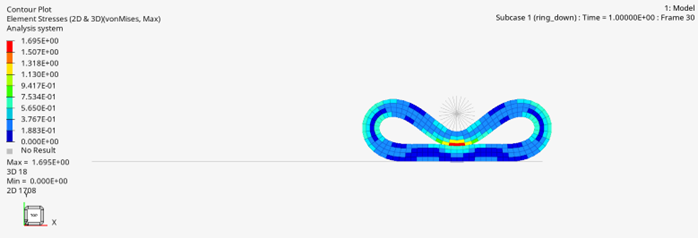
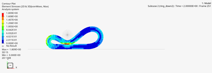
HyperView, select Contour.
For Results Type, in the first drop-down menu, select Element
Stresses (2D & 3D) (t).
For Results Type, in the second drop-down menu, select
vonMises.
Click Apply.
Figure 10. Stress Results for First Load Step Figure 11. Stress Results for Second Load Step
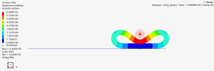
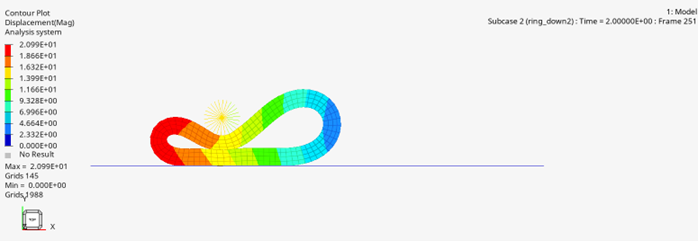
For Results Type, in the first drop-down menu, select
Displacement.
For Results Type, in the second drop-down menu, select
Mag.
Click Apply.
Figure 12. Displacement Results for First Load Step Figure 13. Displacement Results for Second Load Step

 .
.

 .
.