OS-E: 0020 Inline-4 Engine Head
The structural analyses of a cylinder head under various loading conditions can be accomplished by means of finite element analysis using OptiStruct. The results, combined with each analysis concerning the different operating processes of the engine, can be separated mainly into two parts.
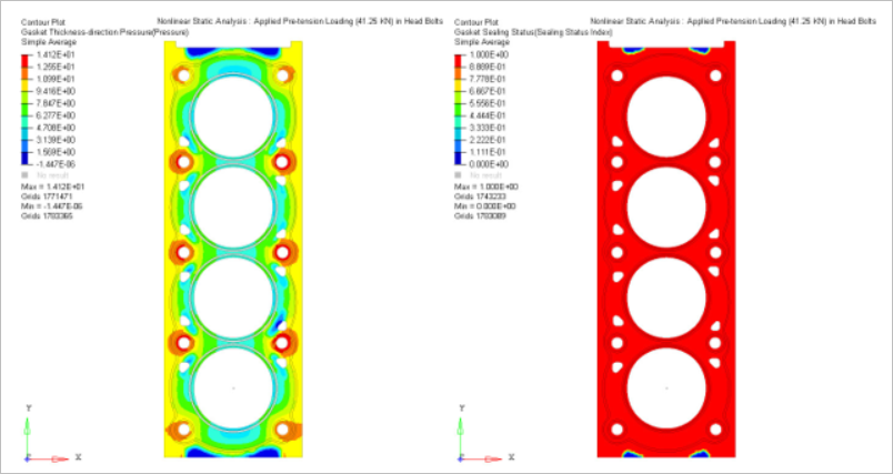
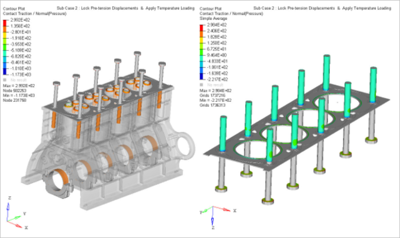
The capacity of gasket sealing mainly depends upon the pre-stressing of the bolts, which are the source of the maximum external loading on the inner structure of the cylinder head.
The location of the weakest contact pressure on the raised portion of the gasket can be transferred as a result of the effect of thermal stress or strain, which may cause the increase in pressure and escaping of the gas.
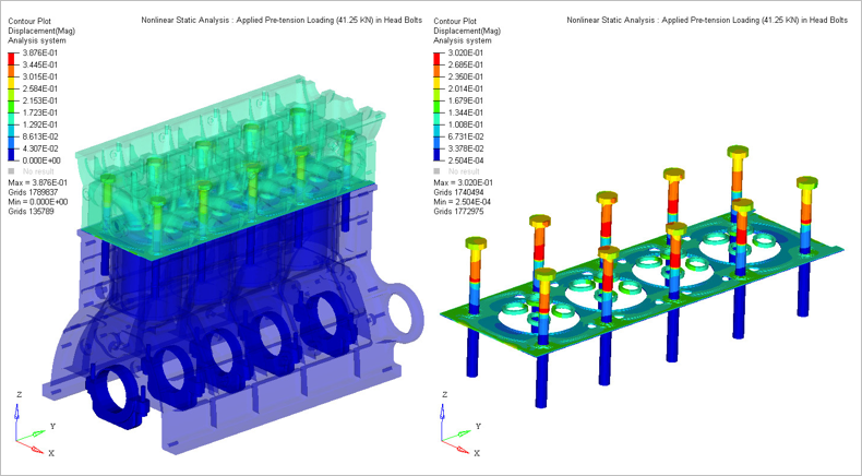
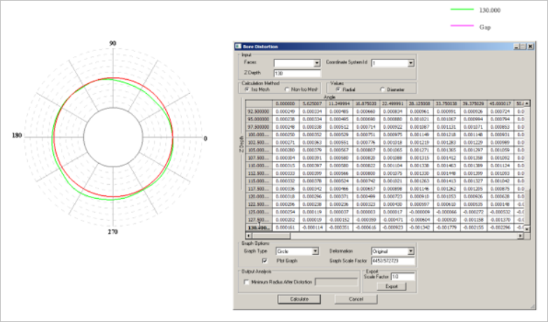
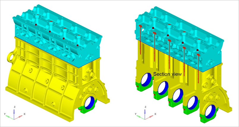
Based on the above use case, Nonlinear Static Analysis is demonstrated for the Altair inline-four engine block model, as shown in Figure 1. The key features such as 3D pretension bolts, gasket material
modeling, friction contact and bore deformations are highlighted.
Note: There are a few
orphan grids in the model, which may lead to some differences in contour results when the
H3D results are plotted in HyperView. If results are different
from what is illustrated in this example, then mask the orphan grids in HyperView and plot the contour again.
Model Files
Before you begin, copy the file(s) used in this example to
your working directory.
Model Description
The analytical procedure could further be divided
into three load steps by means of the superposition principle for simulating various
operating processes of the engine, so the structural analysis are composed of the outputs of
these three load steps.
- FE Model
- Element Types
- CHEXA
The linear material properties are:
- MAT1
- Young’s Modulus
- 21500 MPa
- Poisson's Ratio
- 0.3
- MGASK
- Direct Tensile Modulus
- 0.001
- Transverse Shear Modulus
- 12000
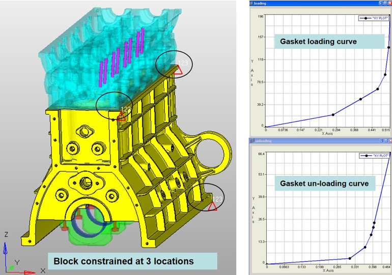
- Assembly Loadings
- The major percentage of the loading applied to the engine is the assembly loading. This mainly refers to the pre-stressing of the bolts, and it plays an important role in preventing gas from escaping from the internal part of the engine.
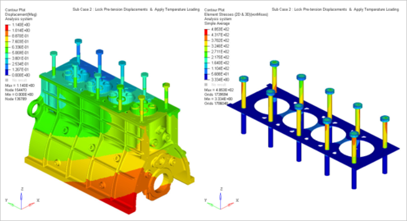
- Thermal Loadings
- In the case of thermal loadings, the nodal temperatures resulting from the prescribed
thermal analysis are assigned to all corresponding nodes of the FEM model of the second
cylinder head in order to calculate the thermal stress/strain of the cylinder head
structure.
Figure 3. Gas pressure 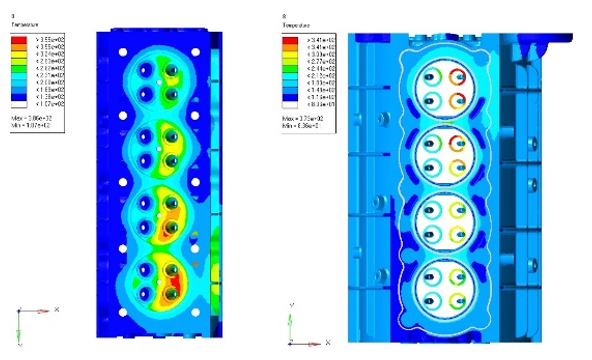
The nonlinear static
analysis material properties are:
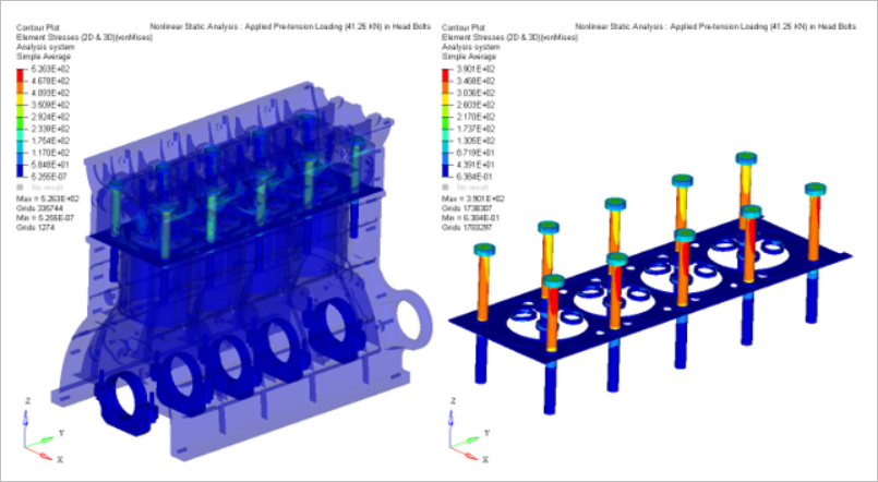
- Case 1
- Assembly Loadings
- Applied pretension loading (41.25 KN) in head bolts
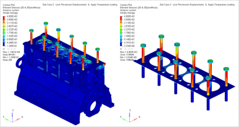
- Case 2
- Thermal Loadings
- Lock pretension displacements
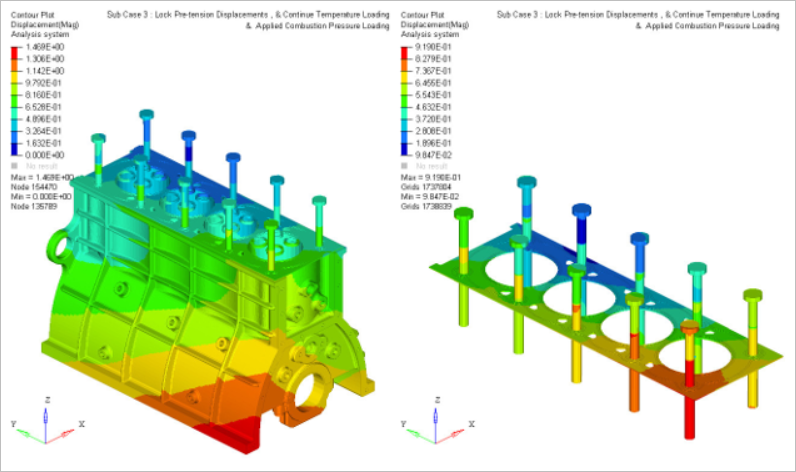
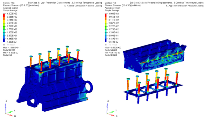
- Case 3
- Gas Pressure
- Lock pretension displacements
Results