MV-7022: Front Suspension Spring - MotionSolve and OptiStruct Co-simulation
Tutorial Level: Advanced In this tutorial, you will use MotionSolve and OptiStruct in a co-simulation to simulate a spring compression and
extension in a short long arms suspension (SLA) system.
Introduction
OptiStruct is a structural analysis solver based on the
finite element method for linear and nonlinear structural problems under static and
dynamic loadings.
A co-simulation between MotionSolve and OptiStruct can simulate non-linear finite element problems,
such as plastic deformation or contact, within a multibody dynamic framework.
Connections between MotionSolve and OptiStruct are accomplished using interface nodes. The
connection type of an interface node is always a spherical joint, meaning only
translational displacements and forces are communicated between the two solvers.
With a combination of spherical joints, it is possible to model revolute and fixed
joint configurations. Currently, other joints are not supported.
The current functionality has the following limitations/requirements:
Only one OptiStruct instance can simulate with a
MotionSolve instance. However, either
instance can entail several flexible bodies.
Only spherical joints can interact between a MotionSolve and OptiStruct system.
When connecting several spherical joints with the OptiStruct system, those cannot be subject to a hard
constraint on the OptiStruct side. In other
words, they cannot be tied together to the same RBE2 or similar
entities.
Any MotionSolve body that is directly connected
to a body in OptiStruct should have significant
mass and inertia to avoid numerical instabilities. Conversely, this
restriction is not required.
Compliant elements, such as springs, forces, bushings, and so on, that are
connected or applied to the OptiStruct body must
be defined in OptiStruct. For example, if a
bushing acts between a body in MotionSolve and a
body in OptiStruct, then the bushing should be
modeled in OptiStruct between the interface node
and the OptiStruct body.
The global frame between MotionSolve and
OptiStruct need to coincide, the
gravitational force needs to act in the same direction, and the units must
match.
An intermediate knowledge of MotionView and MotionSolve is required for this tutorial.
Important: The coupling of MotionSolve with OptiStruct
is in its beta phase (experimental). The feature may contain known or unknown
issues. This tutorial will take approximately 5-7 hours to solve.
Prepare MotionView and Load the Model
Set the environment variable HW_MV_EXPERIMENTAL =
OSFLEX.
Note: The MotionSolve and OptiStruct co-simulation is considered
experimental.
Copy SLA_MS_OS_cosim_start.mdl and
Spring.fem to your working directory.
Launch a new session of MotionView.
From the Standard toolbar, click the Open Model icon,
.
Tip: You can also select File > Open > Model.
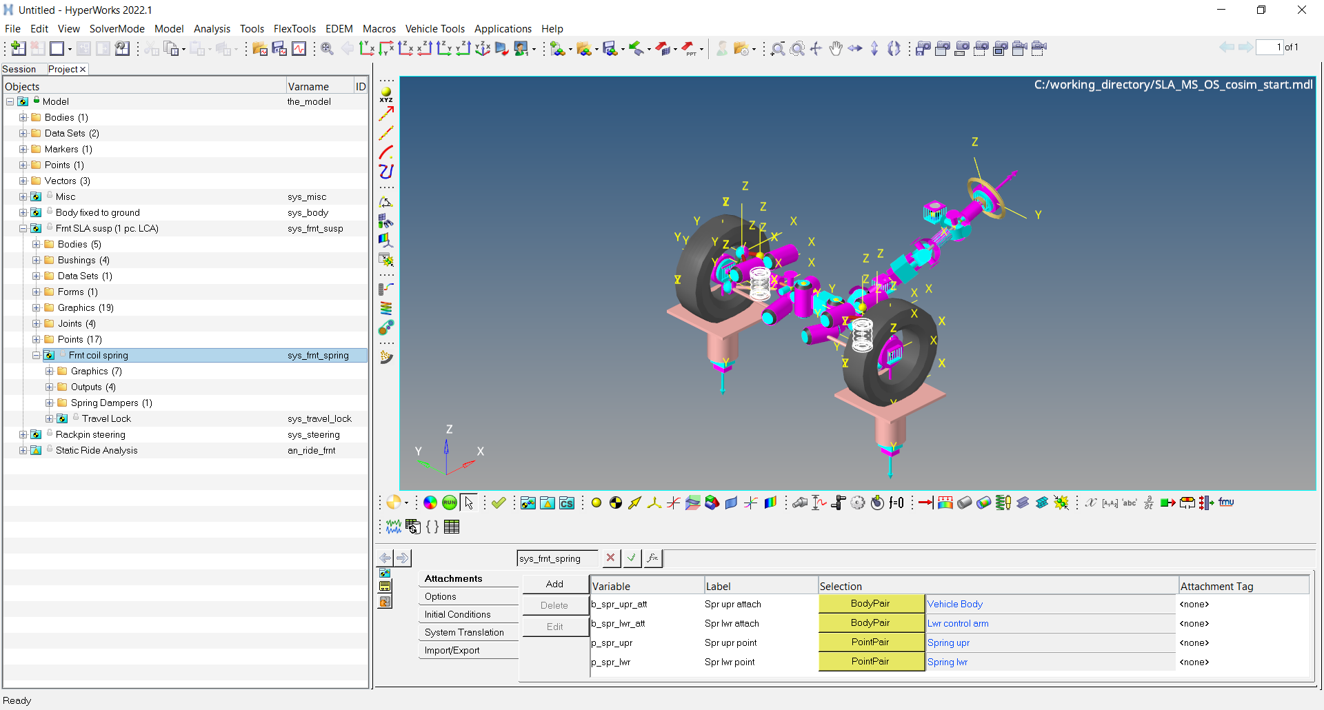
From the Open model dialog, select the
SLA_MS_OS_cosim_start.mdl file from your
<working directory> and click
Open.
Figure 1.
Modify the Model
Remove the old springs pairs. Add one OptiStruct-based
spring on the left side of the vehicle and a simple linear spring on the right side
of the vehicle.
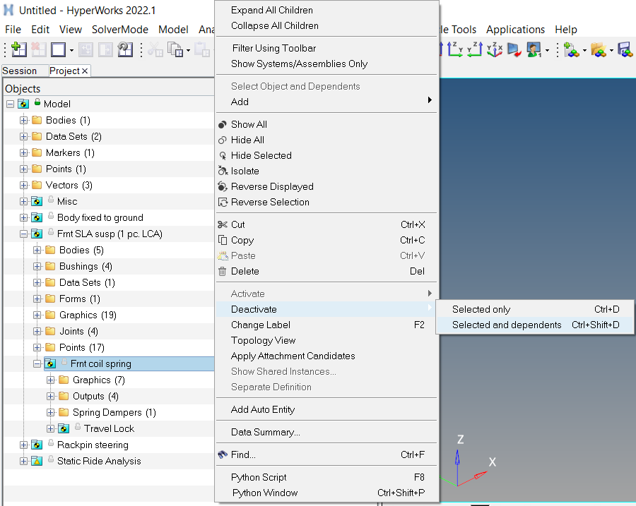
From the Project Browser, under Frnt SLA susp (1 pc. LCA),
deactivate Frnt coil spring and its dependents.
Right-click Frnt coil spring and select Deactivate > Selected and dependents.
Figure 2.
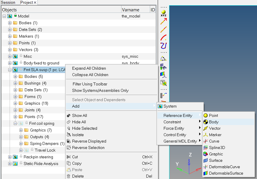
From the Model Browser, right-click Frnt SLA susp (1 pc.
LCA).
For the OptiStruct-based spring, create a body
named OS Spring-Left with type
Single.
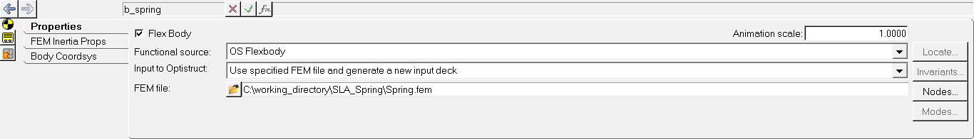
From the Properties tab, select Flex Body.
Change the Functional source to OS
Flexbody.
Verify that Input to OptiStruct is pointing to
Use specified FEM file and generate a new input
deck
From the FEM file browser, select the Spring.fem
file from your working directory.
Figure 3.
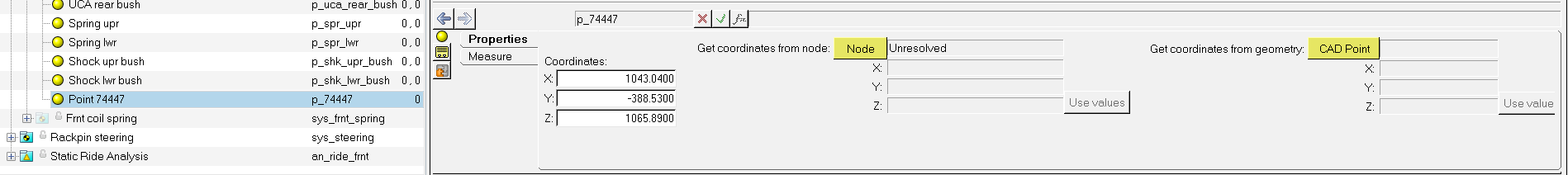
Create a point named Point 74447 with type
Single and with coordinates
1043.04, -388.53,
1065.89.
Figure 4.
Create three ball joints with type Single and with the
connections below:
Label
Body 1
Body 2
Origin
Joint Spring lwr-left
OS Spring-Left
Lwr control arm-left
Spring lwr-left
Joint Spring upr-left
OS Spring-Left
UCA attach body-left
Spring upr-left
Joint at Pt 74447
OS Spring-Left
UCA attach body-left
Point 74447
Tip: Double-click the Body
2 collector to display the Advanced selection dialog.
From the Frnt SLA susp (1 pc LCA) system, select the attachment
UCA attach body-left. UCA attach
body-left resolves to Vehicle
Body.
Select the body OS Spring-Left.
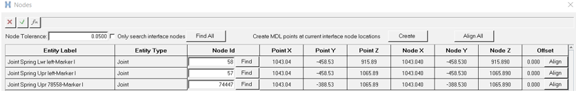
From the Properties Tab, click Nodes. From the Nodes
dialog:
Deactivate the check box Only search interface
nodes.
Click Find All.
Node IDs 58, 57, and 74447 populate for the joint markers.
Figure 5.
Close the Nodes dialog.
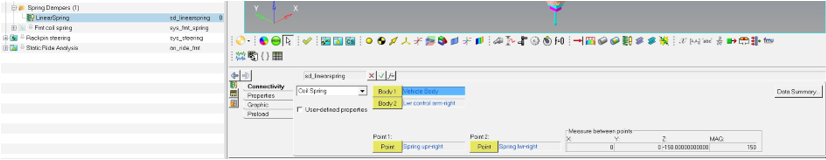
Add a spring on the right side named LinearSpring with
type Single.
From the Connectivity tab, select Coil Spring.
Define the following:
Body 1: UCA attach body-right
Body 2: Lwr control arm-right
Point 1: Spring upr-right
Point 2: Spring lwr-right
From the Properties tab, enter linear value of K =
120 and leave C =
0.
From the Graphic tab, enter Number of Coils = 5
and Radius = 70.
From the Preload tab, enter Force = 7000 and
verify Free length = 150.
Figure 6. The vehicle is fully assembled.
Save the model as SLA_spring_MS-OS.mdl.
Run the Co-Simulation
From the toolbar, select the Run Solver panel. Accept
the default settings and click Run.
MotionView creates a new FEM file for
OptiStruct named
SLA_spring_MS-OS_msoscosim.fem. MotionSolve begins and waits for OptiStruct to be executed.
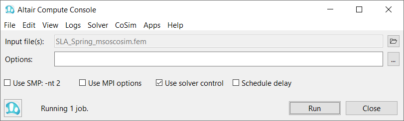
Start an OptiStruct run.
From the Start menu > Altair <version number>, select the Compute Console.
From the Solver menu, select Solvers > OptiStruct.
From the Input file(s) file browser, select
SLA_spring_MS-OS_msoscosim.fem.
Click Run.
The co-simulation begins.Figure 7.
View the results in HyperView.
Overlay the two H3D files: SLA_spring_MS-OS.h3d
and SLA_spring_MS-OS_msoscosim.h3d.

 .
Tip: You can also select .
.
Tip: You can also select .