
Geometry Repair
Tutorial Level: Advanced Use HyperMesh CFD to prepare the geometry of a car for an external aerodynamics simulation.
Initial tasks will be executed manually. Then a template will be created and run to automate most of the pre-processing procedure. Finally, some manual operations will be done to finish the model preparation and transfer it to the case setup environment.
Overview
HyperMesh CFD’s Aerodynamics and Aeroacoustics solutions utilize Altair’s ultraFluidX, an Immersed Boundary, Lattice Boltzmann solver, which allows for increased flexibility in its input geometry as compared to other solvers. Definitions, requirements, recommendations, and considerations related to this input geometry are specified below:
Definitions
- Wetted surface/element
- Portion of the input geometry which will be in direct contact with the flow being simulated
- Solid region
- Region of the domain where the flow shall not be evaluated
- Class-A surfaces or flow-critical surfaces
- Surfaces which are exposed to high-speed flow, large pressure/velocity gradients and/or surround flow-critical gaps
- Baffle surface
- A zero-thickness surface which is immersed in the flow and does not form any enclosed region (it is not part of a solid region)
Requirements
- All elements in the input mesh must be triangles.Note: 1st order triangles are preferred as the solver will ignore any additional information provided by 2nd order triangles.
- The normal vector of all wetted elements must point towards the side of the
element which will be in direct contact with the flow.Note: The simulation will likely run even if the normal vectors are incorrectly assigned. However, unexpected changes to the geometry and/or errors in force measurements would be likely in this case.
- Solid regions may be defined by elements which are not connected, even when gaps exist between these. However, these gaps must be smaller than ½ the size of the voxel (a cubic fluid element) which will intersect the element. Larger gaps may cause the solver to treat the intended solid region as a fluid region.
- Baffle surfaces must be identified as such and in their own separate parts. Note: Usually, we prefer to thicken baffle surfaces to create a solid region.
Recommendations
- Model all heat exchanger cores as Porous Media, which is represented in the input mesh as a rectangular volume with separate inlet, outlet, and wall surfaces. Note: Detailed heat exchanger cores will be accepted by the solver. However, properly calculating the pressure drop across these would vastly increase resource requirements while providing little to no benefit when compared to the alternative.
- Mesh all Class-A surfaces with < 0.1 mm deviation for CAD input
- Limit maximum element size to 50 mm on full-scale vehicles (scale for
scaled vehicles). Note: ultraFluidX will write results directly on the surface elements as defined in the model. If these elements are larger than the surrounding voxels, some results definition will be lost upon writing. ultraFluidX provides an option to automatically split large elements which eliminates the need to limit the element size within the geometry model. This option is addressed in the setup tutorial.
- Wrap (but do not simplify) components whenever a solid region is desired but
gaps or openings exist which would require more than just trivial manual
work to close. Use HyperMesh CFD’s Auto tool when possible to retain
geometry details. Do not use any other Enclosure tool except Auto on Class A
surfaces.Note: In CFD modeling, input parts can have topology issues, like free surfaces and self-intersections, and part assembly issues, such as parts with very close proximity and intersecting parts. Manually connecting these parts can be time consuming and require expertise in certain tools. The Enclosure tool can generate a watertight manifold model from dirty input with considerably less manual work.
Considerations
- ultraFluidX was built to accept complex geometries without issue. Unless a portion of the geometry is being replaced by a model (e.g. heat exchanger core -> porous media), there is no need to simplify the geometry.
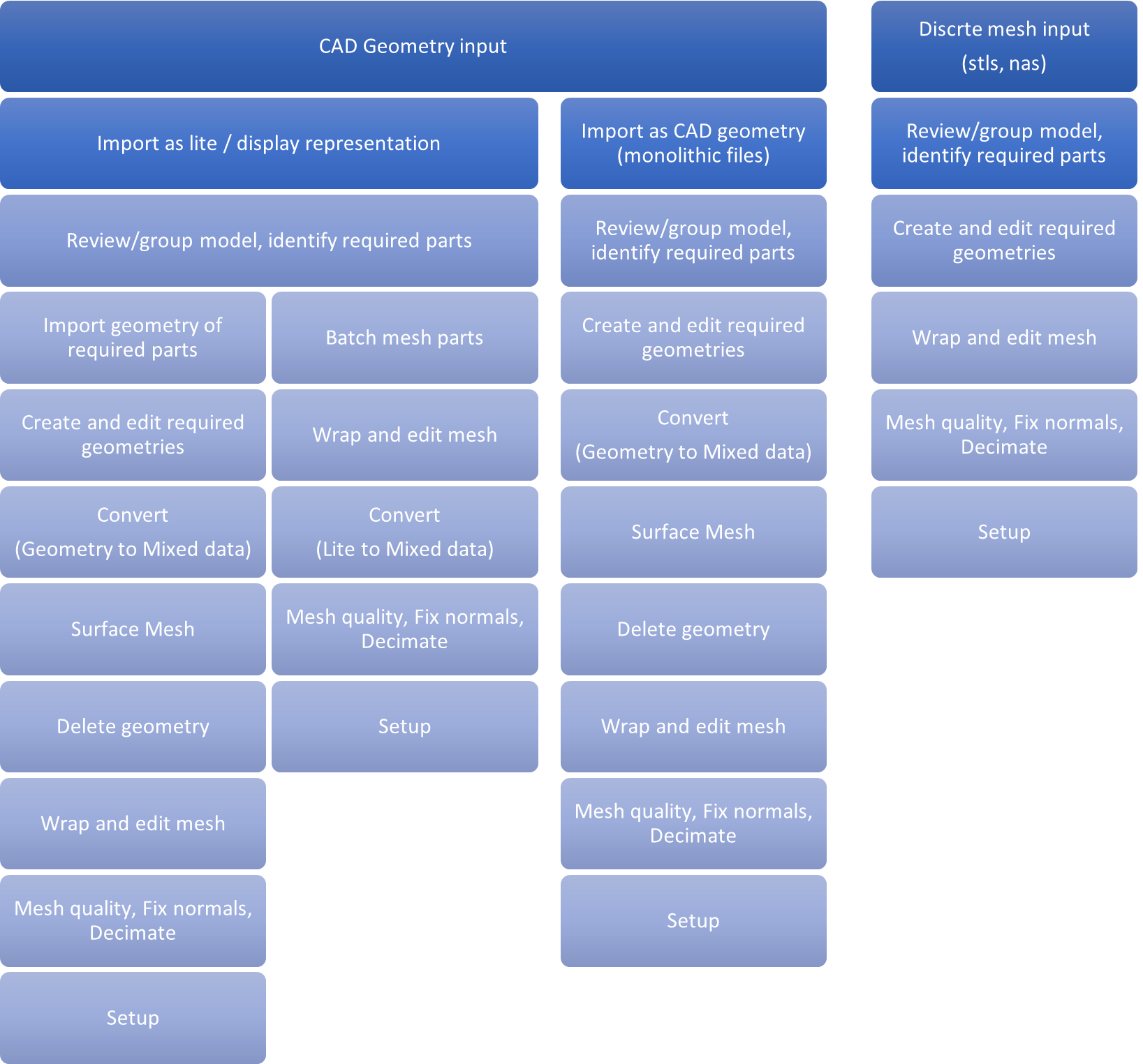
Generic Process Diagram
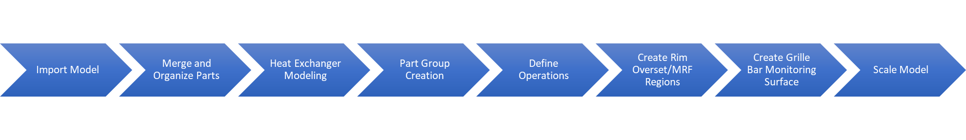
Tutorial Flow
Solution and Environment Selection
File Open
-
From the horizontal toolbar, click .
The File Browser opens.
- From the File Browser, change the file type to Session file (*.hmcfd).
- Navigate to folder, select the Altair_HyperMeshCFD_2025_1_External_Aero_Tutorial_Geometry_Repair_Start.hmcfd file and click Open.
-
From the Units Selection dialog, select MMKS
(mm kg N s) and click Continue.
Figure 4. 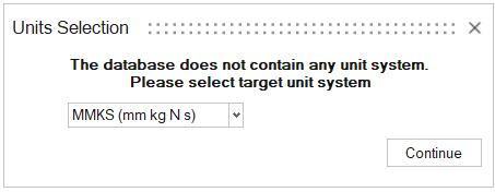
-
From the horizontal toolbar, click .
The File Browser opens.
- From the File Browser, change the file type to STL (*.stl).
-
Navigate to Input Files folder, select all STL files and
click Open.
Figure 5. 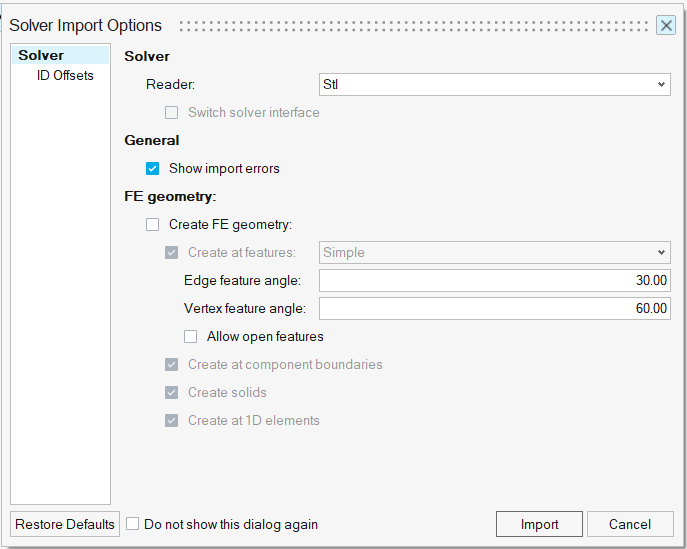 The Solver Import Options dialog opens.
 - Keep default options and click Import.
Part Navigation
Part Browser
Visibility Settings
-
Right-click on an individual assembly/part icon in the browser to show/hide the
specific assembly/part.
Figure 6. 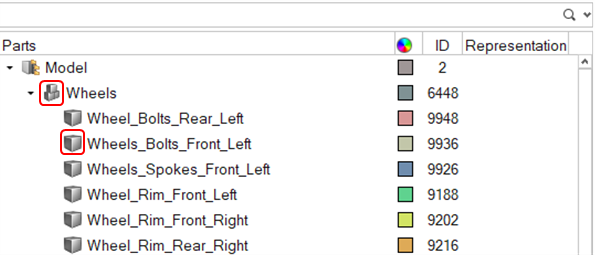
-
Use the Model icon to show/hide the entire model.
Figure 7. 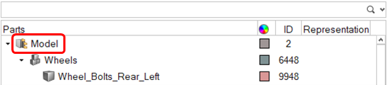
-
Right click on a part/assembly and choose any of the available options.
Figure 8. 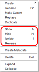
-
Select a part/assembly and press A to show,
H to hide, or I to
isolate.
Note: The previous tasks can also be done for multiple assemblies/parts at once.
Auto-Color
- Select the parts to automatically assign different colors or use CTRL+A to select all displayed parts.
-
On the Part Browser, left click on any of the selected part’s color icon, then
click on the lightning bolt icon.
Figure 9. 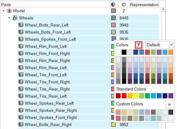
Part Management
Part Organization
Fans
- From the Part Browser, right-click on Model, then select .
- From the Part Browser, right-click on the newly created assembly and rename as Fan_Assembly.
- From the Part Browser, type Fan in the Search bar, then select all parts which do not contain the string "Shroud" in the name, and drag them into the Fan_Assembly assembly.
- Rename each part in the Fan_Assembly assembly by replacing the Cooling_Module string at the start of the name with Fan_Assembly.
- Clear the search bar in the Part Browser.
Wheels
- From the Part Browser, right-click on Model, then select .
- From the Part Browser, right click on the newly created assembly and rename as Wheels.
- Select the four imported wheel assemblies (Wheel_Front/Rear_Left/Right.stl) parts from the Part Browser and drag them into the Wheels assembly.
- From the Part Browser, right click on Model, then select Delete Empty Assemblies.
Heat Exchanger Modeling
Porous Media Boxes
- From the Part Browser, type Core in the Search bar, then isolate the listed parts.
- From the ribbon selection toolbar (horizontal toolbar), click Geometry.
-
From the Geometry ribbon, click on the Simplify Region
tool.
Figure 10.  The Simplify Region guide bar and Simplify Region micro-dialog open.
 - Select the Cooling_Module_Transmission_Oil_Cooler_Core part.
-
From the Simplify Region guide bar, set Create
simplified part in to New Part,
New part name to
Porous_Media_Transmission_Oil_Cooler_Walls, disable
the Save Representation checkbox and then press
Create.
Figure 11. 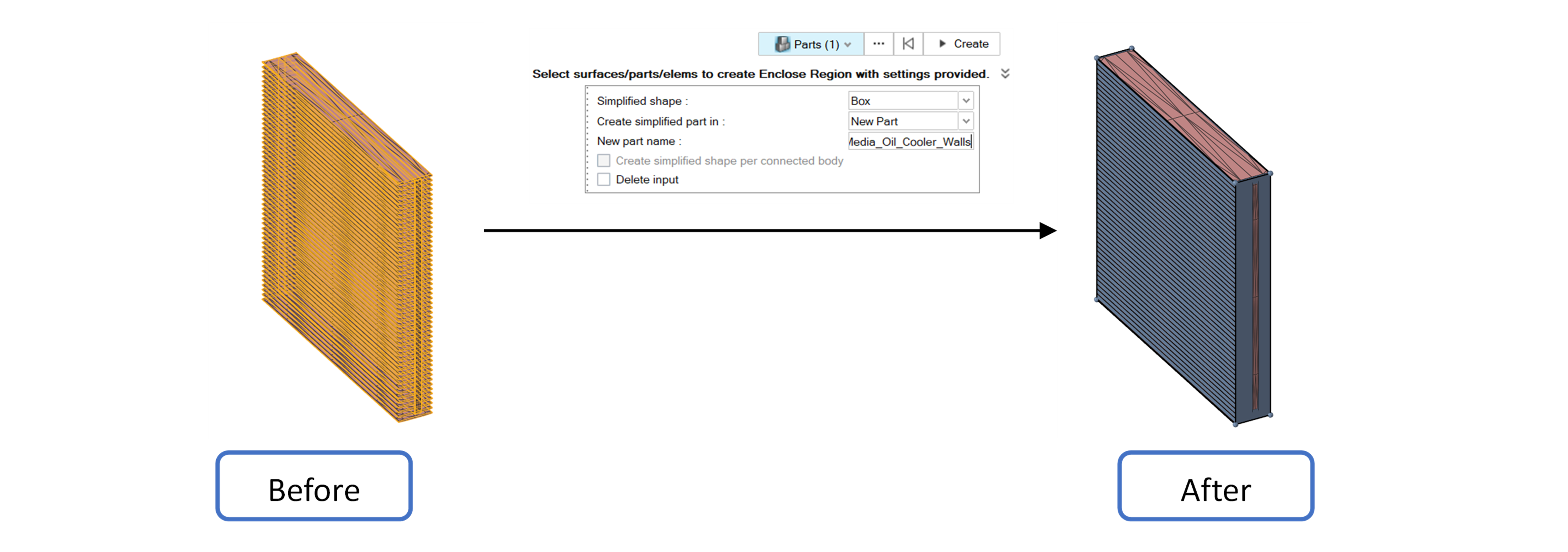
- Repeat Steps 4 and 5 for the Cooling_Module_Low_Temperature_Radiator_Core and the Cooling_Module_Condenser_Core, naming the parts as Porous_Media_Low_Temperature_Radiator_Walls and Porous_Media_Condenser_Walls, respectively.
- Clear the search bar in the Part Browser.
Porous Media Faces
- From the Part Browser, type Walls in the Search Bar, then select and isolate the listed parts.
- From the Part Browser, select Porous_Media_Transmission_Oil_Cooler_Walls, then .
- Clear the search bar in the Part Browser.
-
From the viewer, change the selector to Surfaces, then
click on the inlet surface of the box representing the Transmission Oil Cooler.
Once selected, .
The Create New Part micro-dialog opens.
- From the Create New Part micro-dialog, enter Porous_Media_Transmission_Oil_Cooler_Inlet in the Part name field.
- Repeat Steps 4 and 5 for the outlet surface of the box representing the Transmission Oil Cooler, naming the new part accordingly.
-
Repeat Steps 1-6 for the boxes representing the Low Temperature
Radiator and Condenser, naming the new parts
accordingly.
Note: All parts renamed and created in this section should start with “Porous_Media_” and end in either “_Walls”, “_Inlet”, or “_Outlet”.
- From the Part Browser, right-click on an empty space and select .
- Clear the search bar in the Part Browser.
- Rename the newly created assembly as Porous_Media.
- From the Part Browser, type Porous in the Search Bar, then select all parts shown and drag them in to the Porous_Media assembly.
- Clear the search bar in the Part Browser.
Template Manager
Part Groups
-
From the Geometry Ribbon click on .
Figure 12. 
Figure 13.  The Template Manager dialog opens.Note:
From the Template Manager dialog, groups can be created by either clicking the plus sign or the three dots.
-
From , click the three dots button.
Figure 14. 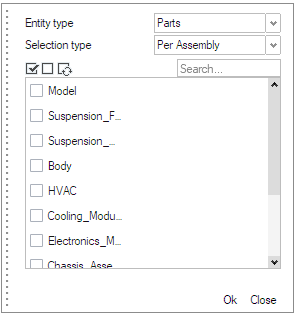 The Group Specification dialog opens.
 -
From the Group Specification dialog, set Entity type to
Parts, Selection type to
Per Assembly, enable the Create group per
selection checkbox, select the Wheels assembly and press
Ok. Then press Close to close the Group Specification
dialog.
Note: The created part group is named Wheels, the same as the selected assembly. The group can be renamed by clicking on the group name and entering a new name.
-
Repeat Steps 2 and 3simultaneously selecting the
Chassis_Assembly, Fan_Assembly,
and Porous_Media assemblies.
Note: Due to the use of the Create group per selection checkbox, three different Part Groups have been created, one for each selected assembly.
- Repeat Step 2 and open the Group Specification dialog.
- From the Group Specification dialog, set Entity type to Parts, Selection type to Per Part and disable the Create group per selection checkbox.
- From the Group Specification dialog, type Wheel_*_Front_Left in the Search bar, then select all parts which do not have the string "Tire" in the name and press Ok. Press Close to close the Group Specification dialog.
- Rename the created Part Group as Rim_Front_Left.
- Repeat Steps 6-8 for the rear left, front right and rear right wheel parts.
-
From , click the plus sign button.
A new row is added to the groups table.
-
From the newly created row, set Group Name as
Body, Type as
Parts, Definition as
By Parts Name, and for Value,
enter a single string containing the part names to be included in the group
divided by commas (no space) as such: Chassis*, Body_Exterior*,
Underbody_Floor, Underbody_Shield_Front, Underbody_Diffuser_Rear_RL7,
Underbody_Tire_Spoiler_*, Patch*.
Note: The wildcard (*) is used to select all parts whose name starts with specific phrases. This is useful when we want to create a group which contains parts from multiple assemblies, but we also want to exclude some parts from that group. For example, notice that when defining the Body part group, the Underbody_Shield_Rear_Baffle part was left out of that part group.
-
Repeat Steps 10 and 11 using the following parameters:
Table 1. Group Name Type Definition Value Powertrain Parts By Assembly Name Suspension_Front,Suspension_Rear, HVAC, Cooling_Module, Electronics_Module, Steering_Module Heat_Exchanger_Cores Parts By Parts Name Cooling_Module _Transmission_Oil_Cooler_Core, Cooling_Module_Low_Temperature_Radiator_Core, Cooling_Module_Condenser_Core -
From , check the Run operations checkbox and
press Run. The parts groups are created. You may view the
newly created groups .
Note: You may color your model by Part Groups using the Model Color tool in the Viewer.
Operations
Delete Heat Exchanger Cores
- From the Template Manager dialog, go to .
-
From , click on the plus sign button
 . The
Operation Definition dialog opens.
. The
Operation Definition dialog opens.
Figure 15. 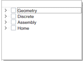 Note: Each of the tabs in the Operation Definition dialog corresponds to each of the available GUI ribbons.
 - From the Operation Definition dialog, expand the Home branch.
-
From the Home branch, select the
Delete operation, then press the ESC key to exit the
dialog.
A new row is added to the table.
- From the newly created row, set Group Selection to Heat_Exchanger_Cores.
-
From the newly created row, click on the Edit button
under the Definition column.
The Operation Definition Parameters dialog opens.
- From the Operation Definition Parameters dialog, enable Delete Entity leaving the Delete Associated Elements option enabled as well. Press ESC to exit the dialog
Merge Rim Parts
- From the Template Manager dialog, go to .
-
From , click on the plus sign button.
The Operation Definition dialog opens.
- From the Operation Definition dialog, expand the Assembly branch.
-
From the Assembly branch, select the Merge/Split
operation, then press the ESC key to exit the
dialog.
A new row is added to the table.
- From the newly created row, set Group Selection to Rim_Front_Left.
-
From the newly created row, click on the Edit button
under the Definition column.
The Operation Definition Parameters dialog opens.
- From the Operation Definition Parameters dialog, set Split/Merge to Merge, then press ESC to exit the dialog.
- Repeat Steps 3-7 for the remaining rim Part Groups (Rim_Front/Rear_Left_Right).
Wrap Wheels and Fix Normals
-
From , click on the plus sign button.
The Operation Definition dialog opens.
- From the Operation Definition dialog, expand the Discrete branch.
-
From the drop-down, select Bulk Operations, then press
the ESC key to exit the dialog.
A new row is added to the table.
- From the newly created row, set Group Selection to Wheels.
-
From the newly created row, click on the Edit button
under the Definition column.
The Operation Definition Parameters dialog opens.
- From the Operation Definition Parameters dialog, enable the checkboxes for CAD wrap parameters, and Fix normal. Within the CAD wrap parameters, enable Split large elements size > and set its value to 10 mm, enable Stitch free edges and set the Stitch tolerance to 0.1 mm, enable Resolve Overlaps and set the Overlap tolerance to 0.1 mm, set the Maximum allowed gap to 4.0 mm, the Baffle treatment to Remove, and the Baffle thickness to 2.0 mm. Within the Fix normal parameters, set the Fix method to By Connectivity.
Cap Chassis
-
From , click on the plus sign button.
- From the Operation Definition dialog, expand the Discrete branch.
-
From the drop-down select Bulk Operations, then press
the ESC key to exit the dialog.
A new row is added to the table.
- From the newly created row, set Group Selection to Chassis_Assembly.
-
From the newly created row, click on the Edit button
under the Definition column.
The Operation Definition Parameters dialog opens.
- From the Operation Definition Parameters dialog, enable the checkbox for Fill holes. Within the Fill holes parameters, enable Consider feature edge loops and set the value of Patch holes threshold to 400 mm.
Wrap Body and Fix Normals
- From , click on the plus sign button.
- From the Operation Definition dialog, expand the Discrete branch.
-
From the drop-down select Bulk Operations, then press
the ESC key to exit the dialog.
A new row is added to the table.
- From the newly created row, set Group Selection to Body.
-
From the newly created row, click on the Edit button
under the Definition column.
The Operation Definition Parameters dialog opens.
- From the Operation Definition Parameters dialog, enable the checkboxes for CAD wrap parameters and Fix normal. Within the CAD wrap parameters, enable Split large elements size > and set its value to 12.5 mm, enable Stitch free edges and set the Stitch tolerance to 0.1 mm, enable Resolve Overlaps and set the Overlap tolerance to 0.1 mm, set the Maximum allowed gap to 5.0 mm, enable Auto seal, set the Baffle treatment to Remove, and the Baffle thickness to 2.0 mm, enable Leak check and set the Enclosure node coordinates to (X: 1900 mm, Y: 0 mm, Z:815 mm). Within the Fix normal parameters, set the Fix method to By Connectivity.
Delete Tiny Parts and Cap Powertrain
-
From , click on the plus sign button.
The Operations Definition dialog opens.
- From the Operation Definition dialog, expand the Discrete branch.
- From the drop-down select Bulk Operations, then press the ESC key to exit the dialog. A new row is added to the table.
- From the newly created row, set Group Selection to Powertrain.
- From the newly created row, click on the Edit button under the Definition column. The Operation Definition Parameters dialog opens.
- From the Operation Definition Parameters dialog, enable the checkboxes for Remove tiny parts, Fill holes, CAD wrap parameters and Fix normal. Within the Remove tiny parts parameters, set Tiny parts bounding box threshold to 21.0 mm. Within the Fill holes parameters, set the patch holes threshold to 100 mm and enable Consider feature edge loops. Within the CAD wrap parameters, enable Split large elements size > and set its value to 15.0 mm, enable Stitch free edges and set the Stitch tolerance to 0.1 mm, enable Resolve Overlaps and set the Overlap tolerance to 0.1 mm, set the Maximum allowed gap to 3.0 mm, set the Baffle treatment to Remove, and the Baffle thickness to 2.0 mm. Within the Fix normal parameters, set the Fix method to By Connectivity.
Wrap Fan Parts and Fix Normals
-
From , click on the plus sign button.
The Operation Definition dialog opens.
-
- From the Operation Definition dialog expand the Discrete branch.
-
From the drop-down, select Bulk Operations, then press
the ESC key to exit the dialog.
A new row is added to the table.
- From the newly created row, set Group Selection to Fan_Assembly.
-
From the newly created row, click on the Edit button under the Definition
column.
The Operation Definition Parameters dialog opens.
- From the Operation Definition Parameters dialog, enable the checkboxes for CAD wrap parameters and Fix normal. Within the CAD wrap parameters, enable Per part wrap, enable Split large elements size > and set its value to 10.0 mm, enable Stitch free edges and set the Stitch tolerance to 0.1 mm, enable Resolve Overlaps and set the Overlap tolerance to 0.1 mm, set the Maximum allowed gap to 4.0 mm, set the Baffle treatment to Remove, and the Baffle thickness to 2.0 mm. Within the Fix normal parameters, set the Fix method to By Connectivity.
Mesh Porous Media Surfaces
-
From , click on the plus sign button.
The Operation Definition dialog opens.
- From the Operation Definition dialog, expand the Home branch.
-
From the drop-down select Surface-Mesh, then press the
ESC key to exit the dialog.
A new row is added to the table.
- From the newly created row, set Group Selection to Porous_Media.
-
From the newly created row, click on the Edit button
under the Definition column.
The Operation Definition Parameters dialog opens.
- From the Operation Definition Parameters dialog, set the Meshing method to Rigid Body, the Average size to 400 mm, the Minimum size factor to 0.1, the Geometric feature angle to 30 deg, the Maximum deviation factor to 0.01 and the Mesh Element Order to First Order.
Run
Template Import/Export
-
To export the template, from the Template Manager dialog, click on the save
button
 on the top of the window.
-
To import a template into the template manager, from the Template Manager
dialog, click on the folder
 button on the top of the window.
- Exit the Template Manager dialog.
MRF/OSM Regions
Volume of Revolution
Spin Surface Generation
-
From the Part Browser, type Caliper
in the Search bar, Isolate the
Suspension_Brake_Calipers_Front and
Suspension_Brake_Rotor_Disc_Front_Left parts, then
clear the search bar and Show the
Wheels assembly.
Note: All tire parts should be named “Wheel_Tire_Front/Rear_Left/Right” and all rim parts should be named “Wheel_Rim_Front/Rear_Left/Right”. Check the part names of the Wheels assembly and if any is wrong, rename it.
-
From the Discrete Ribbon go to to open the Create Topology tool.
Figure 16.  The Create Topology guide bar opens.
 - From the Create Topology guide bar, open the Advanced Selection tool by pressing the button with the three dots.
- From the Advanced Selection tool, set the selection mode to By Part, then type Wheel_Rim in the search bar, group select the filtered parts and press OK.
- From the Create Topology guide bar, press Convert.
-
From the Geometry Ribbon click on the Revolve Region
tool.
Figure 17.  The Revolve Region guide bar opens.
 - From the Revolve Region guide bar, set the selection mode of the Rotating components to Parts then select the Wheel_Rim_Front_Left part.
- From the Revolve Region guide bar, set the selection type of the Non Rotating components to Parts then select the Suspension_Brake_Calipers_Front and Suspension_Brake_Rotor_Disc_Front_Left parts.
-
From the Revolve Region guide bar, press the Axis button
and hover over the wheel rim cap until the axis snaps to the wheel centerline as
shown in the figure below. Once it does, left click to select that as your axis
of rotation.
Figure 18. 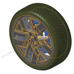
-
From the Revolve Region guide bar, set the Extraction
value to Spin Surface, the
Offset Value from Rotating Region to 9
mm, the Distance from Non Rotating Region
to 3 mm and the New part name
value to VREV_Wheel_Spokes_Front_Left and
disable the Save Representation checkbox, then press
Create.
The spin surface is created.
- Exit the Revolve Region tool.
Spin Surface Editing
- From the Part Browser, select VREV_Wheel_Spokes_Front_Left and Wheel_Rim_Front_Left parts and isolate them.
-
From the Viewer, set the selector to Elements, then
select the elements as shown below in the left side of the figure below and
isolate them.
Figure 19. 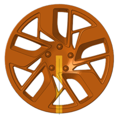
- From the Part Browser, select the VREV_Wheel_Spokes_Front_Left part and show it.
-
From the Viewer’s View Cube select the
Front view. Your viewer should reflect an image
similar to that in the figure below.
Figure 20. 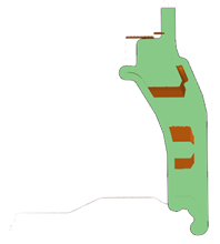
-
From the Geometry Ribbon click on the Split button then
select the Interactive Split tool.
Figure 21. 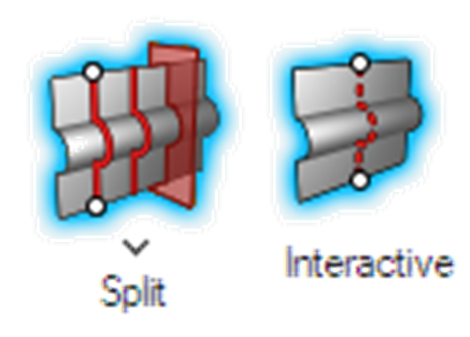
-
Trim the VREV_Wheel_Spokes_Front_Left surface near the hub and rim lip regions
as shown in the left and right images of the figure below.
Figure 22. 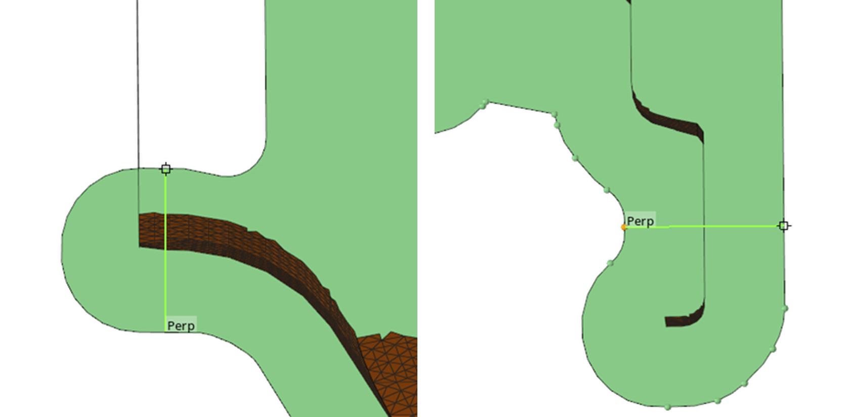
-
Delete the trimmed surfaces as shown in the figure below.
Figure 23. 
Volume Generation
-
From the Geometry Ribbon click on the Spin tool.
Figure 24.  The Spin tool guide bar opens.
 - From the Spin Tool guide bar, set the selector to Surfaces and select the VREV_Wheel_Spokes_Front_Left surfaces.
- From the Spin tool guide bar, click on the hamburger menu to show the tool options and enable Merge solids at shared surfaces.
-
From the Spin tool guide bar, click on the Axis button
and select the centerline of the
VREV_Wheel_Spokes_Front_Left surface as shown in the
figure below.
Figure 25. 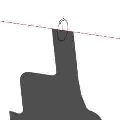 The Spin Input dialog opens.
 -
From the Spin Input dialog, set the spin value to 360
degrees then from the Spin tool guide bar, press the
green check mark to accept. The resulting volume of
revolution should resemble the one shown in the figure below.
Figure 26. 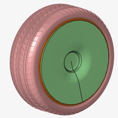
Meshing
- Isolate the newly created volume of revolution.
-
From the Discrete Ribbon click on the Surface Meshing
tool.
Figure 27.  The Surface tool guide bar and Mesh Operations micro dialog open.
 - From the Viewer, select all surfaces in the volume revolution.
- From the Mesh Operations micro dialog, set the Meshing method to Rigid Body, the Mesh size to Maximum Size, the Maximum element size to 20 mm, the Minimum size factor to 0.01, the Geometric feature angle to 15 deg, and the Maximum deviation factor to 0.002, then from the Surface tool guide bar, click Mesh.
- Exit the Surface Meshing tool.
- From the Viewer, set the selector to Surfaces, then select all the surfaces of the volume revolution and delete them with the delete associated elements option set to off.
-
From the Discrete Ribbon, go to to open the Create Topology tool.
The Create Topology guide bar opens.
- From the Create Topology guide bar, click on the hamburger menu and disable Create solids.
- From the Create Topology guide bar, select the VREV_Wheels_Spokes_Front_Left part elements and click Convert.
Duplicate & Move
- From the Part Browser, select the VREV_Wheel_Spokes_Front_Left part, then right click and select Duplicate.
-
From the Home ribbon, select the Move tool.
Figure 28.  The Move tool guide bar opens.
 - From the Move tool guide bar, switch the move method from Interactive to Position, and the selector to Parts, then click on the hamburger menu and enable Show Preview.
- Select the duplicate part to specify that it will be moved, then hide it.
- Show the Wheel_Spokes_Front_Left and Wheel_Spokes_Rear_Left parts.
-
From the Move tool guide bar, click on the Source
button, then select three nodes on the Wheel_Rim_Front_Left
part as shown on the left image of the figure below, then click on the
Target button and select three nodes on the
Wheel_Spokes_Rear_Left part as shown on the right image
of the figure below.
Figure 29. 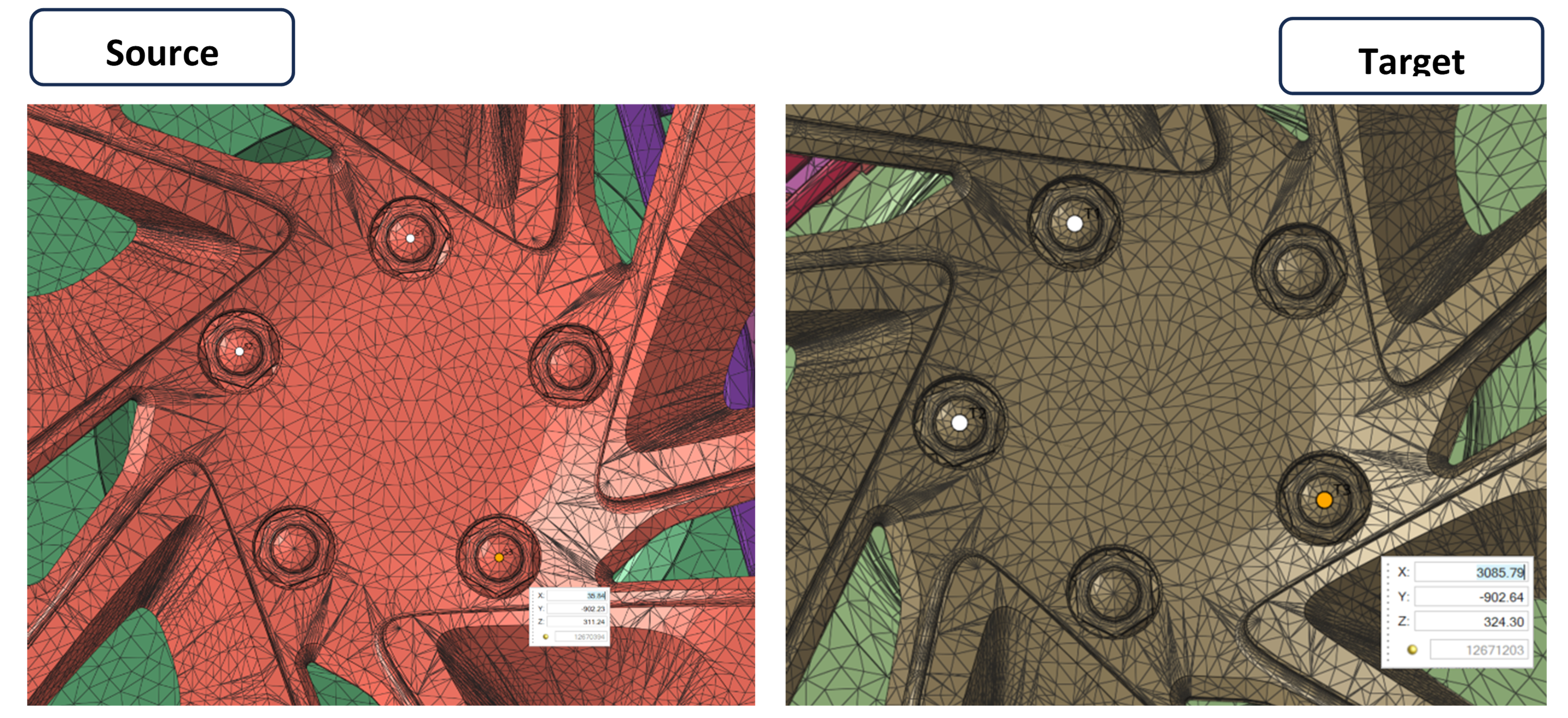
- Inspect the preview and from the Move tool guide bar, click on the green checkmark to apply the positioning.
- Rename the duplicate VREV part VREV_Wheel_Spokes_Rear_Left.
Mirror
-
From the Geometry ribbon go to to open the Mirror tool. The Mirror guide
bar opens.
Figure 30. 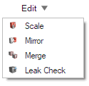
- Show all parts, then select the VREV_Wheel_Spokes_Front_Left and VREV_Wheel_Spokes_Rear_Left parts.
-
From the Mirror guide bar, click on the Plane
button.
The Plane micro dialog opens.
- From the Plane micro dialog, set the plane vector to (X: 0, Y: 1, Z: 0), then click on the XYZ (position) button to specify the origin as (X: 0, Y: 0, Z: 0).
-
From the Plane micro dialog, enable Keep original.
Figure 31. 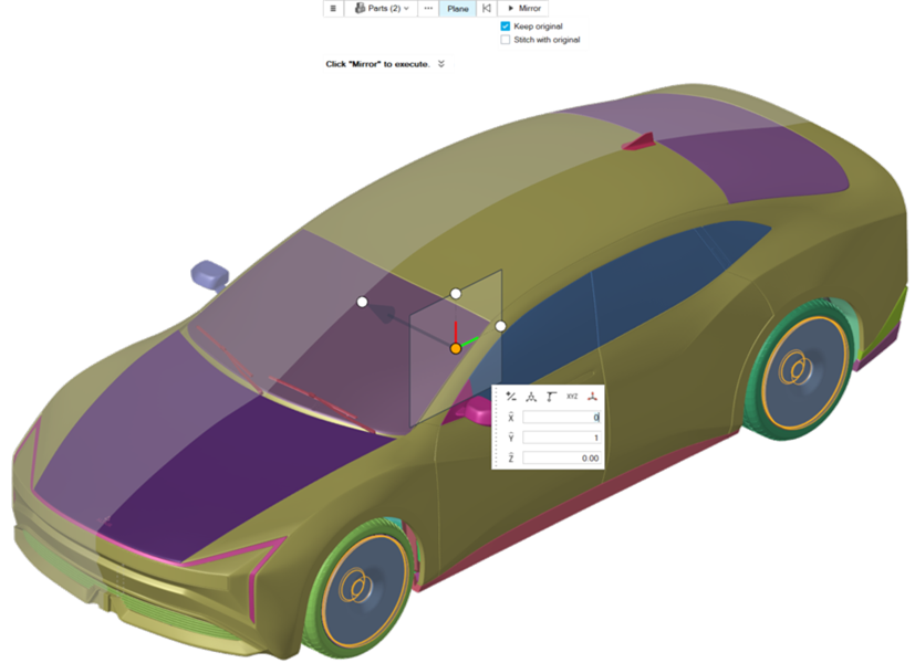
-
Inspect the mirror preview and from the Plane micro dialog, click on
Mirror.
The created parts (mirrored) are connected to each other, not allowing to change their names. The link between them must be broken.
-
From the Assembly Ribbon, go to .
The Assembly Part Browser appears as a tab (named Part) next to the Part Browser tab.
- From the Assembly Part Browser, for each mirrored part, select it separately, then .
- Rename the mirrored VREV parts accordingly and place all VREV parts in a new assembly named VREVs.
Rim Split Wheel Spokes
- Isolate the (total of eight) Wheel_Rim_Front/Rear_Left/Right and VREV_Spokes_Front/Rear_Left/Right parts.
-
From the Geometry Ribbon, click on the Split button then
select the Split Surfaces tool.
Figure 32. 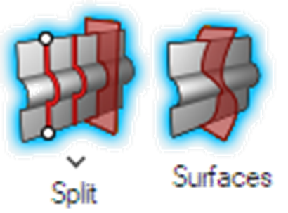 The Split Surfaces guide bar opens.
 - From the Split Surfaces guide bar, click on Target.
- From the Viewer, select one surface from the Wheel_Rim_Front_Left part, then right-click > Select > Attached.
- From the Split Surfaces guide bar, click on tool.
- From the Viewer, select one surface from the VREV_Wheel_Spokes_Front_Left part, then .
- From the Split Surfaces guide bar, activate the Trim both option then click Split.
-
Inspect the trimmed surfaces, then select all surfaces of the
Wheel_Rim_Front_Left part that lie inside the volume of
revolution, and name the part as
Wheel_Spokes_Front_Left. The result should resemble
that shown in the figure below.
Note: After organizing the surfaces to the rim part hide it and inspect if any surfaces have been left out.
Figure 33. 
- Repeat Steps 2-8 for each of the remaining wheels, naming the new parts accordingly.
-
Exit the tool, place all Wheel_Spokes parts in the
Wheels assembly and show all parts.
Note: After all Volumes of Revolution are created, isolate them and from the Model Color tool set the visualization to Surface Normals. In the case where the VREVs outer surfaces have negative Normals, from , select the Normal tool. Set the selector to Parts and select all the VREV parts, the Fix method to By Ray Tracing and Minimum gap size to 5 mm and click on Fix button.
Grille Bars Monitoring Surface
- Select the Body_Exterior_Body part and isolate it.
-
Set the selector to Elements, then right-click anywhere
in the graphics area and activate Polyline select.
Figure 34. 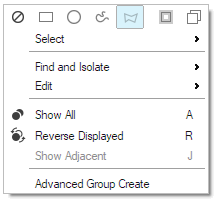
-
Select the body area around the grille bars as shown below and isolate
it.
Figure 35. 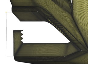
-
From the Geometry ribbon, click on the Simplify Region
tool.
The Simplify Region guide bar and Simplify Region micro-dialog open.
- Set the selector to Elements and select all the displayed elements.
- From the Simplify Region guide bar, set Simplified shape to Convex Fit, Create simplified part in to New Part, set the New part name to Monitoring_Surface_Grille_Bars and disable the Save Representation checkbox..
- From the Simplify Region guide bar, click Create.
- Exit the tool.
- Select the Monitoring_Surface_Grille_Bars part and isolate it.
-
From the Discrete Ribbon click on the Surface Meshing
tool.
The Surface tool guide bar and Mesh Operations micro dialog open.
- From the Mesh Operations micro dialog, set the Meshing method to Rigid Body, the Mesh size to Maximum Size, the Maximum element size to 20 mm, the Minimum size factor to 0.01, the Geometric feature angle to 15 deg, and the Maximum deviation factor to 0.002, then from the Surface tool guide bar, click Mesh.
- Exit the Surface Meshing tool.
- Set the selector to surfaces, then select all the Monitoring_Surface_Grille_Bars surfaces and delete them with the delete associated elements option off.
-
From the Discrete Ribbon go to to open the Create Topology tool.
The Create Topology guide bar opens.
- From the Create Topology guide bar, select the Monitoring_Surface_Grille_Bars part elements and click Convert.
-
Select all surfaces except the front one and delete them with the delete
associated elements option on.
Note: In case the front surface cannot be selected differently from the other surfaces, form the Discrete Ribbon, go to . While in this tool, click on the hamburger menu located on the far left off the Guidebar and change the method from Simple to Connected.
Figure 36. 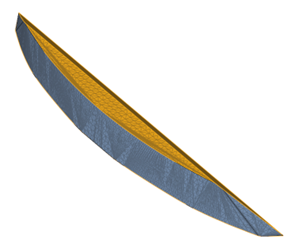
- Show the Body_Exterior_Body and Body_Exterior_Grille_Bars parts.
-
From the Home Ribbon, select the Move tool.
The Move tool guide bar opens.
- From the Move tool guide bar, set the move method to Interactive.
- Select the Monitoring_Surface_Grille_Bars part, click on the Move tab located on the right of the guidebar and then click on the x-axis arrow and move the part in the positive x direction by 29 mm.
-
From the Discrete Ribbon go to to open the Create Topology tool.
The Create Topology guide bar opens.
-
Isolate the Body_Exterior_Body part, then select the
elements as shown in the figure below and click Convert.
Figure 37. 
- Without exiting the tool, isolate the Body_Exterior_Grille_Bars part then, select all elements of that part and click Convert.
- Exit the Create Topology tool.
- Show the Body_Exterior_Body and Monitoring_Surface_Grille_Bars parts.
-
From the Geometry Ribbon click on the
Split button then select the Split
Surfaces tool.
The Split Surfaces guide bar opens.
- From the Split Surfaces guide bar, click on Target.
- From the Viewer, select all the Body_Exterior_Body and Body_Exterior_Grille_Bars surfaces.
- From the Split Surfaces guide bar, click on tool.
- From the Viewer, select all the Monitoring_Surface_Grille_Bars surfaces.
- From the Split Surfaces guide bar, activate the Trim both option then click Split.
- Isolate the Monitoring_Surface_Grille_Bars part.
- Hovering over the part shows that the trim has left some openings. Those need to be closed to get the desired surface. To make them more visible, switch the Mesh visualization to Geometry only.
- From the Geometry Ribbon click on the Split button then select the Interactive Split tool.
- Use the Interactive Split tool to close all openings remaining from the surface split operation.
-
Once all openings are closed, delete all surfaces protruding from the edges
created from the split. Notice that when deleting the surfaces, the delete
associated elements option must be on. The final surface should resemble that
shown in the figure below.
Figure 38. 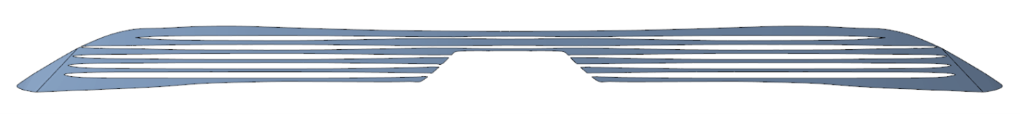 The monitor surface also needs to have a good mesh resolution, so that the desired quantities are monitored correctly. Therefore, a finer surface mesh needs to be generated for it.
 -
From the Discrete Ribbon click on the Surface Meshing
tool.
The Surface tool Guide bar and Mesh Operations micro dialog open.
- From the Viewer, select the Monitoring_Surface_Grille_Bars surfaces.
- From the Mesh Operations micro dialog, set the Meshing method to Surface Deviation, the Mesh size to Average Size, the Average element size to 5.0 mm, enable Curvature based surface refinement, set the Minimum size factor to 0.1, the Geometric feature angle to 22.5 deg, and the Mesh growth rate to 1.3.
- From the Mesh Operations micro dialog, click Mesh.
-
From the Discrete Ribbon, click on the Decimate tool.
The Decimate tool guide bar and Decimate tool micro dialog open.
Figure 39. 
- From the viewer, select the Monitor_Surface_Grille_Bars part.
- From the Decimate tool micro dialog, set Decimate with element size to 1.0 mm and Feature angle constraints to 1.0 deg.
- From the Decimate tool guide bar, click on Decimate.
- Place the Monitor_Surface_Grille_Bars part in a new assembly named Monitor_Surfaces.
Convert Model Units
-
From the graphics window, click on the Global Units
Selector arrow located on the bottom right of the graphical
window to expand all of the units options.
Figure 40. 
- Select MKS (m kg N s).
Data Transfer to Case Setup Environment
-
From the Home Ribbon, click on the Data Transfer
tool.
Figure 41.  The Data Transfer guide bar opens.
 - Select all parts in the model.
-
From the Data Transfer guide bar, click Transfer.
The model is transferred to the Case Setup environment.