HMCFD-T: 3000 Post-Processing
Tutorial Level: Beginner
In this tutorial, you will look at some of the post-processing tools available in HyperMesh CFD. You will use an exhaust manifold model to help explore the various options while post-processing the geometry.
Before you begin, copy the zip file used in this tutorial to your working directory
and extract its contents.
Load the Results in Post
- Navigate to the Post ribbon.
- From the menu bar, select .
-
Navigate to your working directory, select the
Exhaust_Manifold.1.Log file, and click
Open.
The solid and all the surfaces are loaded in the Post Browser.
Figure 1. 
Create Boundary Groups for the Outer Walls of the Manifold
-
Click the Boundary Groups tool.
Figure 2. 
-
Select the walls of the manifold, as shown below.
Figure 3. 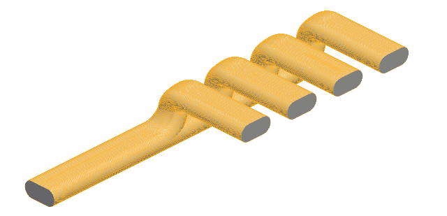
-
In the display microdialog, use the slider to set a
transparency for the model.
Figure 4. 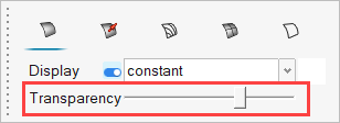
- Click the Contours Line Display tab.
- Turn on the Display.
- Set the Variable to surface y-plus.
- Set the Color to Constant.
-
Change the color to Black.
Figure 5. 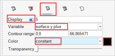
-
On the guide bar, click
 to execute
the command and exit the tool.
- Right-click on Boundary Group 4 in the Post Browser and select Rename from the context menu.
- Rename the boundary group to Walls.
Set Velocity Contours and Vectors on the Inlets and Outlets
- Right-click on the Inlet surface in the Post Browser and select Edit from the context menu.
- In the microdialog, set the Display to velocity.
-
Click
 to refresh the legend.
- Click the Vector Display tab.
- Turn on the Display and set the vector scale factor to 0.003.
-
Set the Color to velocity.
Figure 6. 
-
On the guide bar, click
 to execute
the command and exit the tool.
-
Repeat steps 1-7 for the Outlet surface.
Figure 7. 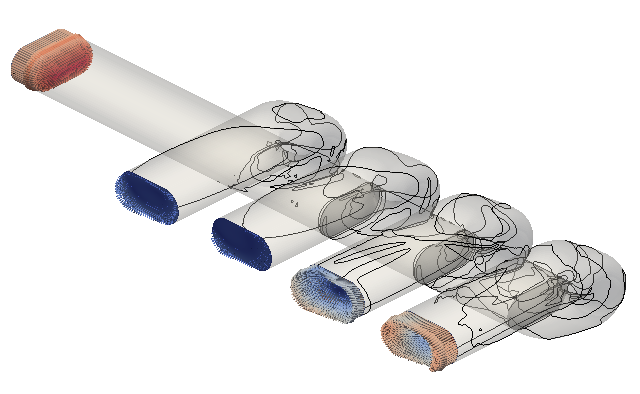
Set Pressure Contours on the Internal Surfaces
- Right-click on the Default Wall surface in the Post Browser and select Edit from the context menu.
- In the microdialog, set the Display to pressure.
- Turn on the Legend.
-
Click
 next to Legend.
- Set the Legend location to Upper Center.
- Set the Legend orientation to Horizontal.
-
Set the Colormap name to Blue Orange.
Figure 8. 
-
On the guide bar, click
 to execute
the command and exit the tool.
Visualize Streamlines from the Inlet
-
Click the Streamlines tool.
Figure 9. 
-
From the secondary ribbon, select the Rectangle
tool.
Figure 10. 
- Select the plane perpendicular to the X-axis as the reference plane for the rectangle.
-
Select the Top face on the View Cube to orient the
model.
Figure 11. 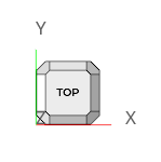
-
Click
 in the microdialog to
active the Move tool.
- Click on the white arrow along the local Y-direction.
-
Enter a value of -0.41 and press Enter.
Figure 12. 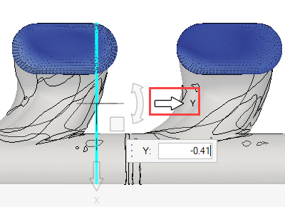
-
Select the Front face on the View Cube.
Figure 13. 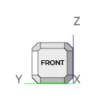
- Click on the white arrow along the local Z-direction.
- Enter a value of -0.11 and press Enter.
- Click on the white arrow along the local X-direction.
-
Enter a value of 0.05 and press Enter.
Figure 14. 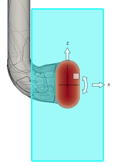
- Press Esc to exit the Move tool.
-
Click
 in the microdialog and set
the length and width to 0.06 and
0.11, respectively.
Figure 15. 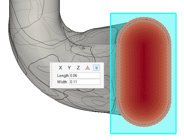
- Click Seeds on the guide bar.
- Set the Generation method to random and the Point count to 100.
- Click Calculate.
- In the microdialog, set the Display to velocity.
- Turn on the Legend.
-
Click
 next to Legend.
- Set the Legend location to Upper Right Corner.
-
Set the Colormap name to Rainbow Uniform.
Figure 16. 
-
On the guide bar, click
 to execute
the command and exit the tool.
Animate Streamlines
- Right-click on Streamlines 1 in the Post Browser and select Animate from the context menu.
-
Click
 on the Animation toolbar.
- Set the number of steps to 50 and choose a desired speed.
-
Click
 to start the animation.
Create a Slice Plane
-
Click the Slice Planes tool.
Figure 17. 
-
Follow steps 3-7 in Visualize Streamlines from the Inlet to
position the slice plane near the inlet then press Esc to exit the Move
tool.
Figure 18. 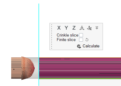
-
Click
 slice plane in the microdialog.
- In the display microdialog, set the Display to velocity.
- Turn on the Legend.
-
Click
 next to Legend.
- Set the Colormap name to Rainbow Uniform.
-
On the guide bar, click
 to execute
the command and exit the tool.
Animate the Slice Plane
- Hide the streamlines from view in the Post Browser.
- Right-click on Slice Plane 1 and select Animate from the context menu.
-
Click
 on the Animation toolbar.
- Set the number of steps to 100 and choose a desired speed.
-
Click
 to start the animation.
Save, Export, and Apply States
- From the menu bar, select .
- Choose a destination to save the file, give it a name, then click Save.
The saved state can be imported anytime post is open with the results file (Log file) loaded. To apply a state to a post-processing instance:
- Right-click on top level (Model_Name) folder in the Post Browser and select Apply State from the context menu.
- Browse to the state file on your machine and click Apply to load the state.