
Template Manager
Use the Template Manager to define rule-based logic for groups, geometric operations, and setup and automate simulation processes.
The Template Manager is useful for:
- Automating the simulation process – since templates are defined based on rules, they can be applied to other models which have the same attributes.
- Defining best practices for meshing and solver parameters and sharing with others
- Parametric studies
-
Click the arrow next to the Home tool set, then
select Template Manager.
Figure 1. 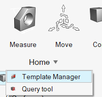
-
Create groups.
Groups allow you to define collections of parts, solids, surfaces, and lines based on rules.
-
Click
 to add a group.
These groups are referenced in the rest of the template categories for selection.
These groups are dynamic; they are evaluated while a specific instance of a category is being evaluated.Figure 2. 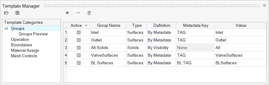
-
Click
-
Define template instances.
-
Click to add a new instance.
When there are multiple types of instances in a category – like Inlet, Outlet, Wall – you can activate multiple instances at a time to create them all in one go.
-
Define the instance and select the group it will act on. Click
 to edit
parameters.
Tip: For the Operation category, the group selection can be either the groups defined in the template manager or pre-defined groupings of geometry.
to edit
parameters.
Tip: For the Operation category, the group selection can be either the groups defined in the template manager or pre-defined groupings of geometry.
Figure 3. 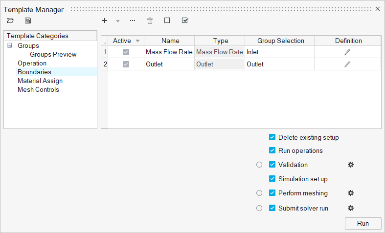
-
Click
-
Select the processes to be executed in sequence.
- Delete existing setup
- If on, the existing setup will be removed.
- Run operations
- If on, it will run the active instances defined in the Operation category.
- Validation
- If on, geometry validation will be performed after running operations or before performing setup, meshing, or solver run.
- Click
 to change the sliver
surface threshold used for validating sliver surfaces and sliver
solids.
to change the sliver
surface threshold used for validating sliver surfaces and sliver
solids. - Simulation set up
- If on, the process will check geometry validity and perform evaluation of active template instances.
- Perform meshing
- If on, and the model is valid, the meshing job will be submitted.
- Click to define batch mesh
settings.
- Submit solver run
- If on, the process will check for model validity and the presence of volume mesh then submit the solver job.
- Click to define AcuSolve launch settings.
- Click Run.
Tip:
- Click
 to export a defined template
or
to export a defined template
or  to import a template.
 - To delete a group or template instance, select it and click

Advanced Creation Options
Create multiple rules for groups, boundaries, mesh controls.
-
Create groupings
-
Click
 .
.
-
Click
-
Create boundaries
-
Click .
-
Click
-
Create mesh controls
-
Click .
-
Click
Perform a Batch Mode Run Using the Template Manager
Run automations in batch mode using template files.
-
Click the arrow next to the Home tool set, then
select Template Manager.
Figure 4.
- Set up your template categories.
-
Click to export the template file.
-
Create a script to open the model file and run based on defined templates.
Use the following Tcl command to run the template manager.
::UserProfiles::HyperWorksCFD::CfdRunAutomation <.hmtpl file path> 2 0 1 0 flag1 1: Surface mesh 2: Surface + Volume mesh flag2 - 0 - retain surface mesh 1 - Redo surface mesh flag3 - volume meshing thread usage: 1 - all threads flag4 - 0 - Do not auto calculate mesh size 1 - Auto calculate mesh size -
Once you define the Tcl file, you can run in
batch mode using the following command:
"C:\Program Files\Altair\<version>\hwdesktop\hm\bin\win64\hmbatch.exe" -tcl <tcl file path>