Define the Mount Limits
You can activate Mount Limits to simulate material contact between the bodies that the bushing connects. This contact limits the bushing deflection. When the deflection is sufficient in a given direction to close the gap distance, the mount limit forces or torques become active. The forces and torque are computed using an impact function. An exponent greater than one (1) provides increasing stiffness with penetration. The damping force is smoothed with a cubic step function over the penetration distance.
- Click Activate to enable the options.
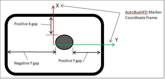
- For Gap, enter a positive real value giving the bushing deflection where the bodies contact. The limit force or torque is zero until the bushing deflection closes the corresponding gap. The dimension is length.
-
For Stiffness, enter a positive real value giving the
limit stiffness for the given direction.
Note: Translation dimensions are force and length-1. Rotational dimensions are force, length, and angle-1.
- In the Exponent field, enter a positive real value giving the power penetration is raised to. An exponent greater than one (1.0) gives increasing stiffness with penetration.
-
For Damping, enter a positive, real value for the
damping coefficient.
Note: Translation dimensions are force, time, and length-1. Rotational dimensions are force, length, time, and angle-1.
- For Penetration, enter a positive, real value giving the penetration at which the damping is fully effective. Damping forces and torques are smoothed by cubic step function over the penetration to prevent discontinuity of the damping force or torque. The dimension is length.