Inlet Regions
Inlet regions mimic the behavior of inlets with a superposed impose region and allow spawning particles anywhere within the computational domain.
Definitions
- Stencil
- Particle arrangement that is put into the domain at inlet region position.
- Spawning
- The act of introducing particle stencils into the domain.
- Spawn interval
- The interval at which the stencil is spawned.
- Extension
- An extended region in the direction of inlet region normal where a constant particle velocity equal to inlet velocity is enforced.
Inlet Region Types
- INREG_CIRCULAR
- INREG_RECTANGULAR
- INREG_CUSTOM
- INREG_CIRCULAR_ARBOR
- INREG_RECTANGULAR_ARBOR
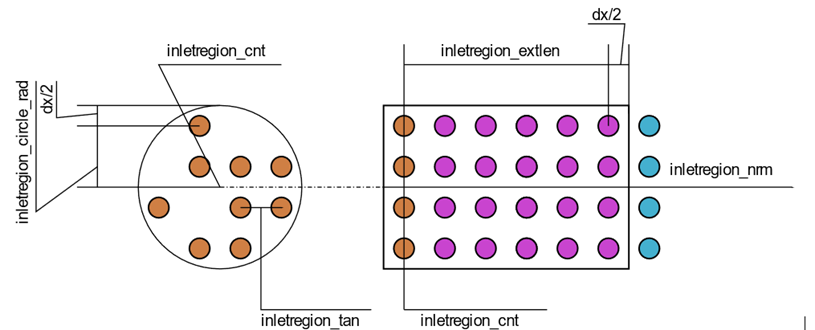
Figure 1 shows schematics of inlet regions and example stencils. Figure 2 and Figure 3 show the relationship between .cfg parameters and inlet regions. It is worth noting that the inlet region type does not define the shape of the stencil but rather the shape of the extension.
Figure 1 shows stencils and extensions for different inlet region types. The top row shows the inlet regions at spawn time while bottom row is at a later time before the next spawn time. (a) Rectangular inlet region with complete stencil. (b) Circular inlet region with partial stencil. (c) Custom inlet region. Particles are color coded as brown for spawned particles, magenta for particles affected by the extension and cyan for free particles. Continuous lines show extension borders.
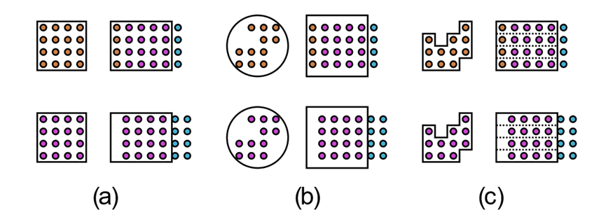
Figure 2 shows rectangular and Rectangular_Arbor inlet region definitions, color coded as Figure 1. Note that extension is half dx larger on each side compared to cfg definition. Since there is not a particle on the center of the stencil, the case shown here either had its inletregion_meshmatch set to true or was provided with an inletregion_stf_file. (left) front view, flowing into page; (right) side view, flowing left to right.
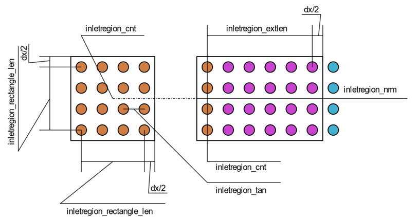
Figure 3 shows circular and Circular_Arbor inlet region definitions, color coded as Figure 1. Note that extension is half dx larger on each side compared to cfg definition. Since the stencil does not fill the region, the case shown here was provided with an inletregion_stf_file. (left) front view, flowing into page; (right) side view, flowing left to right.
There are two methods for defining the inlet region stencil for Rectangular and Circular types, including Arbor (arbitrary orientation) variants. The first method is to ask the inlet region to create the stencil and the second method is to provide a stencil file. While the former method leads to a stencil fitting the inlet region type (Figure 1-a), the stencil shape in the latter method is not restricted by the inlet region type (Figure 1-b).
| INREG | Internal Stencil | Stencil File | Extension Shape | Orientation | Movement |
|---|---|---|---|---|---|
| CIRCULAR | Circle | Any shape | Cylinder | Global x, y, z | Static |
| RECTANGULAR | Rectangle | Any shape | Cuboid | Global x, y, z | Static |
| CUSTOM | Not available | Any shape | Matches stencil | Global x, y, z | Static |
| CIRCULAR ARBOR | Circle | Any shape | Cylinder | Arbitrary | Static/moving |
| RECTANGULAR ARBOR | Rectangle | Any shape | Cuboid | Arbitrary | Static/moving |
Auxiliary Files
- Stencil file, inletregion_stf_file
- Time-velocity series file, inletregion_tvs_file
Stencil file includes the particle stencil to be spawned by the inlet region. The particle stencil should be planar. All particles in the stencil file should be inside the domain box defined by min_domain and max_domain to spawn. Stencils may have three (x-position, y-position and z-position) or four columns (x-position, y-position, z-position, and phase). The four-column stencil is only used for multiphase stencils.
Time-velocity series (.tvs) files are used for inlets with time dependent velocity. The expected velocity magnitude of inlet region at times of interest are given in the tvs file and the solver linearly interpolates the velocity magnitude values between the given points. The .tvs file has two columns: (1) time and (2) velocity magnitude.
Basic Operation
- Stencil spawn surface
- Extension (can be turned off)
- Spawn a stencil with the velocity in sync with fluid.
- Integrate the velocity in time to estimate the position of the spawned stencil.
- Once the current spawn has moved by dx, spawn the next layer.
- The extension imposes the inlet velocity and ensures the distance between different spawn layers remain at dx.
All particles spawned by the inlet region belong to the FLUID phase the moment they appear in the simulation. Inlet regions have an internal storage of the complete stencil on each rank and away from the simulation. This may result in more memory consumption for very large stencils. For Arbor type inlet regions, all transformations are applied to this internal stencil storage.
- Misaligned stencil and conduit:
- As the fluid particles leave the extension, the distance between fluid-fluid particles and fluid-wall particles are not similar. This results in a pressure rise on the side where fluid particles are closer to the wall. Depending on the severity of the misalignment, this may result in undesired secondary flows.
- An angled conduit discretized in Cartesian with an arbor type inlet region:
- As well as experiencing the same problem as the above item, this case will face an additional issue. Since the conduit cross section changes in the direction of inlet region normal, the extension will push the particles through the conduit wall. It is not guaranteed that the particles will be out of the wall at the end of the extension.
The extension covers up to half dx, further in each direction than the definitions given in the cfg to ensure all spawned inlet region particles are covered. If extension definitions are missing from the cfg and are detected automatically based on the given stencil, the extension covers up to half dx, further from the outermost stencil particle.
While possible, not using an extension is generally not recommended unless it is guaranteed that the spawn area will remain undisturbed during the active interval of the inlet region. For example, it is acceptable to disable the extension when the inlet region is stationary and sprays into void. Moving inlet regions always require an extension to function properly.
For inlet regions that are not discharging into void, it is recommended that all sides except for the front of the inlet region (where fluid particles exit the extension) be encapsulated. It is possible to leave the back side of the inlet region uncovered as well, provided that no other particles disturb the stencil spawn surface.
- Creating multiple superposed inlet regions with separate stencils.
- Creating multiple superposed inlet regions with a multiphase stencil.
It is important to pay attention to (cnt, circle_rad) and (cnt, rectangle_len) parameter pairs when creating multiphase Circular and Rectangular type inlet regions, respectively. Ideally, the extension should not cover outside of the conduit walls.
- Assume two Circular inlet regions, where one phase has a circular stencil and the other has an annular stencil encompassing the first. These inlet regions will be called INREG1 and INREG2. The cnt} of both inlet regions should be place at the center of stencils. The circle_rad of INREG1 may only cover up to the circle radius, or the outer radius of INREG2. The cnt of INREG2 should cover the outer radius of the annular stencil.
- Assume two Circular inlet regions, INREG1 and INREG2, where each phase has one half of a circular stencil. Combining these two stencils results in a complete circle. In this case, cnt should be at the center of combined stencils of INREG1 and INREG2 and circle_rad should be equal to the distance from cnt to the outermost particle of either stencil.
Limitations
- Inlet regions are not checked for collision with each other to allow for multiphase inlet regions.
- Arbor and Custom inlet regions do not check for collision with domain box.
- Arbor inlet regions do not support meshmatch option.
- An inlet region does not impose a force on its base.
- Inlet regions do not support backflow.
- Inlet regions do not support velocity profiles. It is recommended to use an extended conduit if a fully developed profile is needed.