Frame Suite
Description of the sliding frame functionality as a part of the nanoFluidX frame suite feature.
Frame suite is a feature targeting water wading applications in nanoFluidX to facilitate the simulation of experiment-like conditions at a reasonable computational cost.
General Frame Definitions
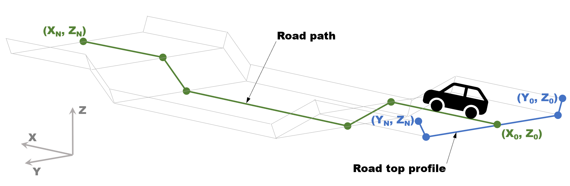
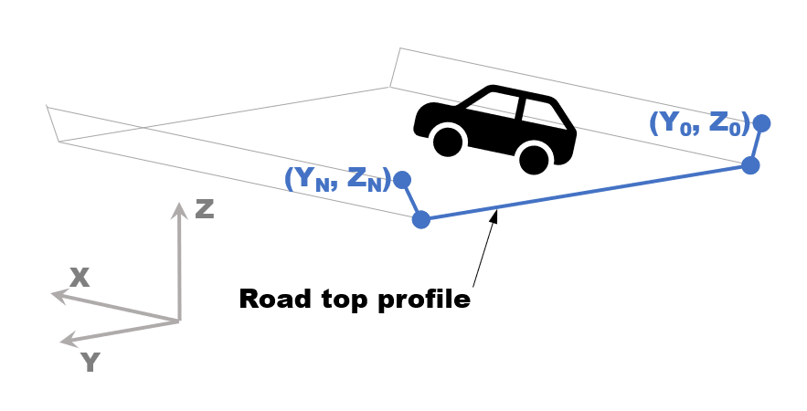
- Road Top Profile Stencil
- A set of Y and Z coordinates which defines the road top section profile.
- Road Path Stencil
- A set of X and Z coordinates which defines the road path in the direction of the moving vehicle.
- Spawning
- The act of introducing particle stencils into the domain as the frame is moving along the specified vehicle path.
Sliding Frame
Sliding frame is a part of the frame suite feature targeting water wading applications in nanoFluidX. To facilitate the simulation of experiment-like motion of descending into a water filled channel at a reasonable computational cost, sliding frame follows a phase of interest during simulation by moving the computational domain and spawning fluid and road particles as necessary.
There are two modes in which the sliding frame follows the phase of interest. In line lock mode, the sliding frame translates in the X direction only, and in point lock mode, the sliding frame follows both X and Z translational movement of the phase of interest. While the phase of interest may move arbitrarily, the trajectory of the sliding frame is confined to the XZ plane.
Temporal (Static) Frame
The temporal frame is intended for use cases where the car is moving inside a channel or a part of it with a flat road path and constant water depth, which is a quasi steady state problem. Therefore, the case setup can be further streamlined and optimized in such a way, that the reference frame does not have to follow a moving car body as reference object, but the motion can be imposed through a velocity boundary condition on the road and an inlet-like boundary condition for fluid particles while keeping the car body stationary (similar to belt systems in wind tunnels).
Contrary to sliding frame, which translates the domain based on the motion of an obj_phase of type MOVINGWALL, the relative motion of the car and the road is imposed by defining a motion for the road_phase of type WALL. Note that the only supported motion is IMPOSE_VEL, with a velocity vector parallel to the X coordinate, where a negative value corresponds to the car moving forward relative to the road. Due to the path being flat and therefore predefined, the road definition is simplified and only the top profile, which defines the top side of the road in the YZ plane in absolute Y and Z coordinates, is required. A separate definition of a road path is not necessary and therefore is removed.
Road/Channel Definition
The road definition is split into two parts: the road path, which defines the elevation of the road in the XZ plane, and the road top profile, which defines the top side of the road in the YZ plane.
It is recommended that both road top profile and road path point coordinates (which define road path and profile lines) are provided in absolute coordinates. Also, you should align the road top profile with the car at the start of the simulation, meaning the road should be close to or touching the tires.
- Is a two column file of the Y Z form.
- Consists of a minimum of two Y Z pairs (two points defining one line segment).
- Has a strictly increasing Y coordinate. Every value in the first column must be bigger than that of the previous line.
- Is a two column file with X coordinate in the first and Z coordinate in the second column.
- Consists of a minimum of two X Z pairs (two points defining one line segment).
- Has a strictly increasing X coordinate.
Freeze and sponge layers