Drivetrain Oiling Simulation
Geometry Cleanup and Model Organization
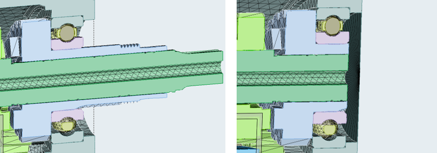
If you have a gear-train assembly with protruding shafts or axles, make sure you cut them up such that they are slightly offset inward from the wetted surface of the housing.
- Bearings are fairly large and there are only a handful of rolling elements
- Best practice: Leave the bearings and the rolling elements as they are, no need for any simplification.
- Bearings are medium in size and have a considerable cage that holds the rolling elements
- Best practice: Remove the cage. The remaining space will typically allow
for some flow through the bearing.
Figure 2. . Full bearing geometry, including the cage on the left. Simplified bearing geometry with removed cage on the right. With moderate resolution, typically several particles can pass between the rolling elements. 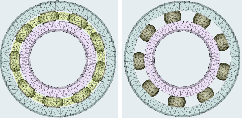
- Many small rolling elements with or without the cage
- Best practice: Remove every other rolling element to create sufficient space in the bearing for the flow to go through. Remove the cage as well, if present.
- Option 1: keep the entire bearing static.
- Option 2: keep the outer ring static and move the rolling elements and the inner ring at the same RPM as the shaft/axle.
- Option 3: keep the outer ring static and move the rolling elements at half the RPM of the shaft/axle and the inner ring at the same RPM as the shaft/axle.
While technically option 3 is the most accurate representation, it is also introducing several additional steps during the pre-processing (more motion definitions, introduction of another nanoFluidX phase). Given that completely accurate flow through bearings is typically beyond the reach of the most common nanoFluidX simulations option 2 provides the best trade off between invested pre-processing time and accuracy of the solution.
Technically, it is possible to define the planetary motion of each individual rolling element, but without sufficiently high resolution (extreme resolution), such pre-processing detail would not bring much in terms of solution quality.
Solution Settings
- Particle Spacing
- Ideally aim to resolve the tip of the gear (have 3 particles at the tip of the gear tooth). However, in reality this is not always practical as it results in an excessive no. of particles. Under-resolved tips start to behave as a porous media, since they would be partially transparent to the surrounding particles. In the majority of cases, it is tolerable to have 2 particles at the gear tooth tip as there is minimal influence on the flow field.
- Simulation Duration
- For drivetrain applications, it is recommended to simulate 100-150 rotations of the gears. Typically, this results in a duration between 0.5 and 10 s physical time.