Skew
Overview
 |
|
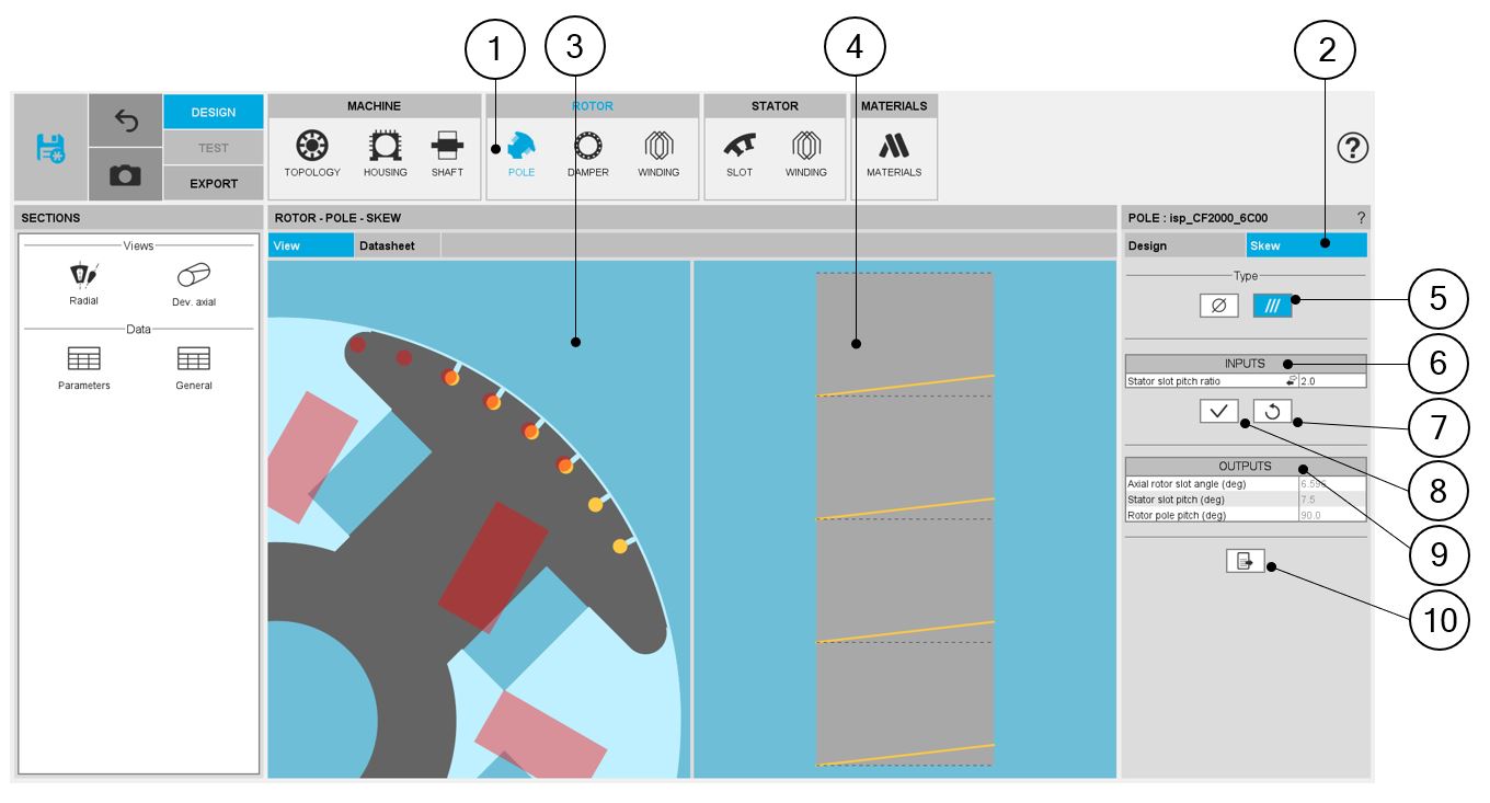
| POLE – SKEW design area | |
| 1 | Selection of the ROTOR subset: POLE panel (click on the icon POLE) |
| 2 | The Skew tab indicates the tool to define the pole skew angle |
| 3 | Visualization of the machine radial view to visualize the pole skew |
| 4 | Visualization of the rotor developed view to visualize the pole skew |
| 5 | Choices to define a skew: None – Continuous (Continuous in our example) |
| 6 | Skew inputs to be defined |
| 7 | Buttons to restore the default input values. |
| 8 | Buttons to validate the inputs (pressing the “enter key” twice applies inputs too). |
| 9 | Skew outputs (read only) |
| 10 | Button to export the skew data into *.txt or *.xlsx files. |
Set a skew angle
 |
|
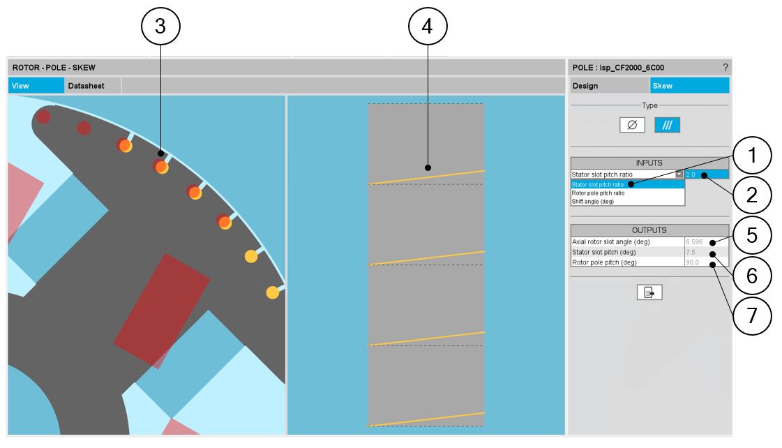
| How to set a skew angle? | |
| 1 | Choose the definition mode of the skew: Stator slot – Rotor slot – Shift angle |
| 2 | Definition of the skew angle, depending on the definition mode |
| 3 | Visualization of the chosen skew angle on the machine radial view |
| 4 | Visualization of the equivalent axial slot angle on the rotor developed view |
| 5 | Equivalent axial rotor slot angle (read only) |
| 6 | Equivalent stator slot pitch (read only) |
| 7 | Equivalent rotor slot pitch (read only) |
Note: The user can add a skew angle on the rotor or on the stator. If
a skew is already defined in the stator when setting a skew on the rotor, the stator
skewing will be automatically reset to “None”.